
A high-temperature resistant ultra-short cavity distributed reflection single-frequency fiber laser and its manufacturing method

A fiber laser and distributed reflection technology, used in lasers, laser parts, phonon exciters, etc., can solve problems such as differences in refractive index and temperature resistance, reduce cavity length, ensure temperature resistance, and increase complexity sexual effect

Active Publication Date: 2021-01-19
XI AN JIAOTONG UNIV
View PDF9 Cites 0 Cited by
  • Summary
  • Abstract
  • Description
  • Claims
  • Application Information

AI Technical Summary

Problems solved by technology

[0004] The object of the present invention is to provide a high-temperature-resistant ultra-short cavity distributed reflection single-frequency fiber laser and its manufacturing method, using high-reflectivity common FBG and tilted FBG as the high-reflectivity cavity mirror and output cavity mirror of the laser, to overcome The problem of the difference in the refractive index and temperature resistance of the two gratings in the existing DBR preparation technology

Method used


Image

  • A high-temperature resistant ultra-short cavity distributed reflection single-frequency fiber laser and its manufacturing method
  • A high-temperature resistant ultra-short cavity distributed reflection single-frequency fiber laser and its manufacturing method
  • A high-temperature resistant ultra-short cavity distributed reflection single-frequency fiber laser and its manufacturing method

Examples


Embodiment 1

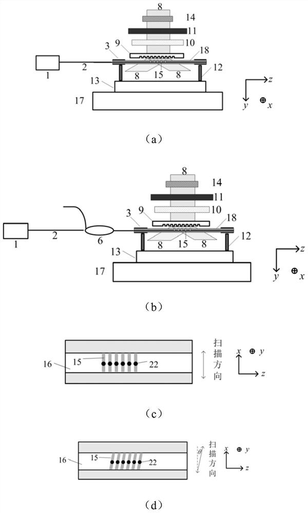
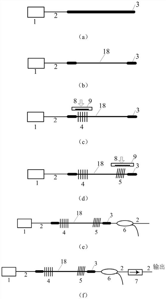
[0056] This embodiment takes the preparation of an ultra-short cavity erbium-doped fiber distributed reflection fiber laser as an example, and the manufacturing steps and laser structure are as follows image 3 As shown, the details are as follows:

[0057] Material: Erbium-doped fiber Liekki Er80-8 / 125, mask period 2142nm, 976nm single-mode semiconductor laser pump source;

[0058] (1) The pigtail 2 of the laser pump source 1 is fused together with a section of erbium-doped optical fiber, as image 3 As shown in (a).

[0059] (2) Strip the active optical fiber coating near the fusion point by about 2 cm with a wire stripper, and fix the active optical fiber stripped of the coating on the three-dimensional piezoelectric nano-displacement stage 13 with an optical fiber clamp 12, such as image 3 Shown in (b).

[0060] (3) The femtosecond laser 8 is incident on the cylindrical lens 10 through the optical shutter 14 and the variable attenuator 11. After being focused by the cy...

Embodiment 2

[0066] This embodiment takes the fabrication of a short-cavity distributed reflection fiber laser on an ytterbium-doped active fiber as an example, such as Figure 5 As shown, the details are as follows:

[0067] Material: Ytterbium-doped active fiber SM-YSF-HI, mask period 1485nm, 976nm single-mode semiconductor laser pump source;

[0068] (1) The pigtail 2 of the laser pumping source 1 is fused together with the pump end of the wavelength division multiplexer 6, and the common end of the wavelength division multiplexer 6 is fused with a section of ytterbium-doped active optical fiber with a length of 4 cm. See Figure 5 Medium (a)

[0069] (2) Strip the active optical fiber coating near the fusion point by about 2 cm with wire strippers, and fix the active optical fiber stripped of the coating on the three-dimensional piezoelectric nano-displacement stage 13 with an optical fiber clamp 12, see Figure 5 In (b).

[0070] (3) The femtosecond laser 8 is incident on the cylin...

Embodiment 3

[0075] This embodiment takes the example of making a short-cavity distributed reflective fiber laser on an erbium / ytterbium co-doped active fiber, as follows:

[0076] Material: Erbium / ytterbium co-doped active fiber EYDF-6 / 125-HE, mask period 2142nm, 976 nm single-mode semiconductor laser pump source,;

[0077] (1) The pigtail 2 of the laser pump source 1 is fused together with the pump end of the wavelength division multiplexer 6, and the common end of the wavelength division multiplexer 6 is co-doped with an erbium / ytterbium active fiber with a length of 4 cm, See Figure 5 Medium (a)

[0078] (2) Use wire strippers to strip off the erbium / ytterbium co-doped active fiber coating near the fusion point by about 2 cm, and fix the stripped active fiber on the three-dimensional piezoelectric nano-displacement stage with the fiber clamp 12 13, see Figure 5 Middle (b).

[0079] (3) The femtosecond laser 8 is incident on the cylindrical lens 10 through the optical shutter 14 a...


PUM

PropertyMeasurementUnit
reflectanceaaaaaaaaaa

Abstract

The invention discloses a high-temperature-resistant ultra-short cavity distribution reflection type single-frequency fiber laser device and a manufacturing method thereof. The laser device comprisesa laser device pumping source, an active optical fiber, a high-reflectivity common fiber bragg grating, an inclined fiber bragg grating, a wavelength division multiplexer and an optical isolator, wherein the high-reflectivity common fiber bragg grating and the inclined fiber bragg grating are etched on the active optical fiber, the high-reflectivity common fiber bragg grating and the inclined fiber bragg grating are respectively used as a resonant cavity high-reflectivity cavity mirror and an output cavity mirror, the reflectivity of the output cavity mirror is set by selecting an inclinationangle of the inclined fiber bragg grating, and the high-reflectivity common fiber bragg grating and the inclined fiber bragg grating are respectively inscribed on an active optical fiber core throughvertical and inclined scanning by using a femtosecond laser phase mask method. The laser device is advantaged in that passive optical fibers can be prevented from existing in a resonant cavity, high gain during single-frequency output is guaranteed, the cavity length of the resonant cavity is reduced to the maximum extent, femtosecond laser inscribing is adopted, the laser device can be suitable for various active optical fibers, and the prepared optical fiber laser device is suitable for the high-temperature environment within 550 DEG C.

Description

technical field [0001] The invention belongs to the fields of fiber optics and fiber laser, and relates to a method for preparing a high-temperature-resistant short-cavity single-frequency fiber laser, in particular to a high-temperature-resistant short-cavity distributed reflective fiber laser based on an inclined fiber Bragg grating and a manufacturing method thereof. Background technique [0002] Short-cavity distributed reflective (DBR) fiber lasers have important applications in sensing measurement and microwave photonics. The all-fiber DBR laser with fiber Bragg grating (FBG) as the resonator mirror has the advantages of small size and good stability. [0003] The resonant cavity of DBR fiber laser using FBG, the high reflectivity cavity mirror adopts high reflectivity FBG, and the output cavity mirror adopts low reflectivity ordinary FBG as the laser output terminal. FBG is generally written in photosensitive optical fiber by ultraviolet light, and its reflectivity i...

Claims


Application Information

Patent Timeline
Patent Type & Authority Patents(China)
IPC IPC(8): H01S3/067H01S3/00
CPCH01S3/0064H01S3/067
Inventor 陈涛司金海范春松侯洵
Owner XI AN JIAOTONG UNIV
Learn More