System and method for treating ammonia-nitrogen wastewater

A technology of ammonia nitrogen wastewater and treatment system, applied in the field of pollutant treatment, can solve the problems of low biological treatment efficiency, unstable treatment effect, difficult organic wastewater treatment, etc., achieve high pollutant removal rate and reduce the content of nitrogen oxides , The effect of reducing the burden on the equipment

Pending Publication Date: 2020-02-25
JIANGSU XINHE AGROCHEM
4 Cites 0 Cited by

AI-Extracted Technical Summary

Problems solved by technology

[0008] However, the process of pure chemical treatment of wastewater is complicated, and it needs to add a variety of additional components at the same time, the cost is high, and the treatment effect is unstable
[0009] For the treatment of high ammonia nitrogen wastewater, the current treatment methods include biological nitrification and denitrification, breakpoint chlorination, gas stripping, precipitation and ion exchange methods, and then the biological method uses the metabolism of mi...

Abstract

The invention provides a system and a method for treating ammonia-nitrogen wastewater. The system for treating ammonia-nitrogen wastewater comprises a preheating unit, a multi-effect evaporation unit,a gas-liquid separation unit and a concentrate combustion unit; the discharge port of the preheating unit is connected with the feed port of the multi-effect evaporation unit, the gas discharge portof the multi-effect evaporation unit is connected with the gas-liquid separation unit, and the liquid outlet of the multi-effect evaporation unit is connected with the concentrate combustion unit; andthe concentrate combustion unit comprises a concentrate combustion device, a heat exchange device and a tail gas treatment device which are connected in sequence. The ammonia-nitrogen wastewater is concentrated, and the obtained concentrate is combusted to recycle the ammonia-nitrogen wastewater; and the system has the advantages of low energy consumption, high pollutant removal rate, and positive effect on environmental protection.

Application Domain

Water contaminantsEmission prevention +4

Technology Topic

Exhaust gasPollutant +5

Image

  • System and method for treating ammonia-nitrogen wastewater

Examples

  • Experimental program(1)
  • Effect test(5)

Example Embodiment

[0069] Example 1
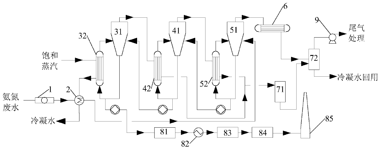
[0070] This embodiment provides an ammonia nitrogen wastewater treatment system. The schematic structural diagram of the ammonia nitrogen wastewater treatment system is as figure 1 As shown, it includes: a filter device 1, a preheating unit 2, a three-effect countercurrent evaporator, a gas-liquid separation unit and a concentrated liquid combustion unit.
[0071] The discharge port of the preheating unit 2 is connected with the feed port of the three-effect evaporator 51 in the three-effect countercurrent evaporator, and the condensate outlet of the three-effect evaporator 51 in the three-effect countercurrent evaporator is connected with the gas-liquid separation unit , The liquid outlet of the one-effect evaporator 31 in the three-effect countercurrent evaporator is connected to the concentrated liquid combustion unit through a jacketed pipe.
[0072] The concentrated liquid combustion unit includes a direct-fired furnace 81, a heat exchanger 82, an SCR reactor 83, a spray tower 84 and a chimney 85 which are connected in sequence. The liquid outlet of the one-effect evaporator 31 in the three-effect countercurrent evaporator is connected to the direct-fired furnace 81 in the concentrated liquid combustion unit through a jacketed pipe.
[0073] The preheating unit 2 is a shell-and-tube heat exchanger.
[0074] The one-effect preheater 32 of the three-effect counterflow evaporator is connected with an external heat source heating pipe, which is connected to the one-effect preheater 32 and then connected to the preheating unit 2, so that the external heat source is After the one-effect evaporator 31 provides heat, it then provides heat for the ammonia nitrogen wastewater, thereby improving the energy utilization rate.
[0075] The filtering device 1 is a precision filter with a filtering aperture of 0.5 mm or less.
[0076] The gas-liquid separation unit includes a condensate intermediate tank 71, a gas-liquid separation tank 72, and a vacuuming device connected in sequence. The heat source outlet pipes of the two-effect preheater 42 and the three-effect preheater 52 in the three-effect countercurrent evaporator are independently connected to the condensate intermediate tank 71; the condenser in the three-effect countercurrent evaporator 6 The liquid outlet is connected to the gas-liquid separation tank 72. The vacuum pump 9 is a vacuum pump 9 for pumping non-condensable gas in the gas-liquid separation tank 72.
[0077] The ammonia nitrogen wastewater is filtered in the filter device 1, and then flows into the preheating unit 2 for preheating. The preheated ammonia nitrogen wastewater flows into the three-effect countercurrent evaporation unit for evaporation and concentration, and the concentrated liquid flows into the concentrated liquid combustion unit for combustion and combustion. The latter gas undergoes exhaust gas treatment after heat exchange to reduce the nitrogen oxide content in the exhaust gas. The evaporative gas of multi-effect evaporation is condensed and separated from gas and liquid, and then the condensate is recovered, which realizes the resource utilization of ammonia nitrogen wastewater, and the energy consumption in the treatment process is low, and the pollutant removal rate is high.
[0078] The invention adopts a three-effect countercurrent evaporator to evaporate and concentrate the preheated ammonia nitrogen wastewater, wherein the gas phase and liquid phase materials flow countercurrently. The flow direction of the liquid phase is as follows: the preheated ammonia nitrogen wastewater first enters the three-effect evaporator 51, exchanges heat in the three-effect preheater 52, and enters the separation chamber of the three-effect evaporator 51 for gas-liquid separation; After being concentrated to a certain concentration in the effect evaporator 51, the three-effect transfer pump is sent to the two-effect evaporator 41 for evaporation and concentration; after the ammonia nitrogen wastewater is concentrated to a certain degree in the two-effect evaporator 41, the two-effect transfer pump It is sent to the one-effect evaporator 31 for evaporation and concentration, and after the concentration reaches the process requirements, it is transported to the direct-fired furnace 81 in the concentrated liquid combustion unit by the one-effect transfer pump.
[0079] The gas flow direction is: saturated steam enters the first-effect preheater 32 for heat exchange and condensation, and the condensate flows into the preheating unit 2 to preheat the ammonia nitrogen wastewater; the secondary steam generated by the first-effect evaporator 31 is used as the heat source of the second-effect preheater 42 , And condense in the two-effect preheater 42; the secondary steam produced by the two-effect evaporator 41 is used as the heat source of the three-effect preheater 52, and condensed in the three-effect preheater 52; The secondary steam is condensed in the condenser 6, and the condensate flows into the gas-liquid separation unit. Among them, the condensate of the two-effect preheater 42 and the three-effect preheater 52 flows into the condensate intermediate tank 71 and then flows into the gas-liquid separation tank 72; the condensate in the condenser 6 directly flows into the gas-liquid separation tank 72 and is used in the vacuum pump The non-condensable gas is recovered under the action of 9.

PUM

no PUM

Description & Claims & Application Information

We can also present the details of the Description, Claims and Application information to help users get a comprehensive understanding of the technical details of the patent, such as background art, summary of invention, brief description of drawings, description of embodiments, and other original content. On the other hand, users can also determine the specific scope of protection of the technology through the list of claims; as well as understand the changes in the life cycle of the technology with the presentation of the patent timeline. Login to view more.

Similar technology patents

Paint used for coiled metal material

Owner:ZHEJIANG TRANSFER PAINT CO LTD

Continuous slurry polymerization volatile removal

InactiveUS6858682B2increase ethylene concentrationreduce energy consumption
Owner:EXXONMOBIL CHEM PAT INC

Virtual thermostat for a zonal temperature control

InactiveUS9644857B1reduce energy consumptionimprove thermal comfort
Owner:ASHGRIZ NASSER +1

Wireless sensor network node device used in underground coal mine

InactiveCN101621431AReduce energy consumptionextended life cycle
Owner:CHINA UNIV OF MINING & TECH

Classification and recommendation of technical efficacy words

  • Reduce energy consumption

Preparation method of high-strength hydrogel

InactiveCN103739861AThe preparation process takes a short timeReduce energy consumption
Owner:HENAN POLYTECHNIC UNIV

Catalyst for gas phase hydrogenation of acetic acid to prepare ethanol

Owner:DALIAN INST OF CHEM PHYSICS CHINESE ACAD OF SCI +1

Wireless emergency lighting system

ActiveUS8491159B2ease of installationreduce energy consumption
Owner:RING LLC
Why Eureka
Try Eureka