Ceramic impeller
An impeller and ceramic technology, applied in the field of rotary power pump equipment, can solve the problems of crack generation, difficult to enlarge the impeller, poor impact resistance, etc., and achieve the effect of improving impact resistance, reducing the probability of damage, and improving wear resistance.
- Summary
- Abstract
- Description
- Claims
- Application Information
AI Technical Summary
Problems solved by technology
Method used
Image
Examples
Embodiment 1
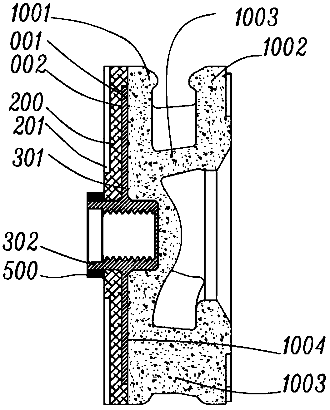
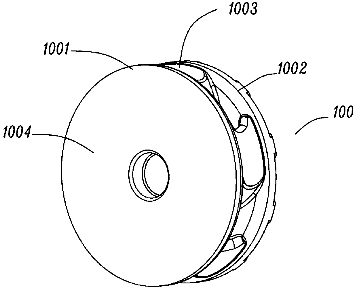
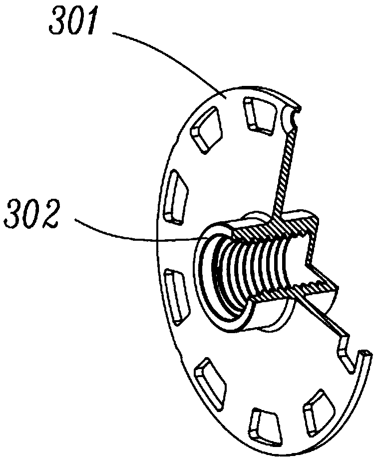
[0057] The specific embodiment of the present invention is as Figure 1 to Figure 4 As shown, the impeller is a closed impeller with a diameter of 301 mm. The driving cover plate 1001, main blade 1003 and driven cover plate 1002 of the impeller are a ceramic body sintered with alumina, and the metal layer 301 is a circle with an outer diameter of 270 mm, namely Its radial dimension is 0.9 times the diameter of the impeller, and the axial thickness of the metal layer 301 is 5mm; the material of the second driving cover plate 200 is alumina ceramics, and the second auxiliary blade 201 is arranged on the outside thereof, and the second driving cover plate 200 The axial thickness including the second auxiliary blade 201 is 20mm; the material of the metal layer 301 and the mandrel 302 is 45# steel, the first adhesive energy-absorbing layer 001 and the second adhesive energy-absorbing layer 002 are acrylic adhesives, The thickness is about 0.2-0.5mm, and the shaft sheath 500 and the...
Embodiment 2
[0061] Specific embodiment 2 of the present invention refers to Figure 5-9 As shown, the diameter of the impeller is 390mm, including the impeller body 100 made of silicon carbide ceramics, the metal layer 301 made of 45# steel, and the shaft handle 302. The handle 302 and the main shaft are screwed together, the radial dimension of the metal layer 301 is 235mm, which is 0.6 times the diameter of the impeller, the axial thickness of the metal layer 301 is 6mm, and several axial through holes 3011 are arranged on it. The plate 1001 is provided with an adhesive surface 1004 bonded to the metal layer 301, and a second drive cover 200 is provided on the outside of the metal layer 301. The thickness of the second drive cover 200 is 12 mm. The impeller body 100, metal Layer 301, the second driving cover plate 200 and the first adhesive energy-absorbing layer 001 and the second adhesive energy-absorbing layer 002 are bonded into a whole, and the first adhesive energy-absorbing layer...
Embodiment 3
[0066] like Figure 10As shown, the diameter of the impeller is 450 mm, and the threaded protrusion 3012 is connected to the metal layer 301. The side of the driving cover 1002 is respectively the driving cover 1002, the first adhesive energy-absorbing layer 001, and the metal layer from the inside to the outside. 301, the second adhesive energy-absorbing layer 002, the second driving cover plate 200, the first adhesive energy-absorbing layer 001 and the second adhesive energy-absorbing layer 002 are filled with adhesive, and carbon fiber mesh impregnated with resin is pasted or other fiber webs. A second driven cover plate 10021 is arranged on the outer side of the driven cover plate 1002, a third adhesive energy-absorbing adhesive layer is formed between the driven cover plate 1002 and the second driven cover plate 10021, and the third energy-absorbing There is a carbon fiber mesh impregnated with resin in the bonding layer 003 to improve strength. This embodiment can be u...
PUM
| Property | Measurement | Unit |
|---|---|---|
| diameter | aaaaa | aaaaa |
| thickness | aaaaa | aaaaa |
| thickness | aaaaa | aaaaa |
Abstract
Description
Claims
Application Information
 - R&D
- Intellectual Property
- Life Sciences
- Materials
- Tech Scout
- Unparalleled Data Quality
- Higher Quality Content
- 60% Fewer Hallucinations
Browse by: Latest US Patents, China's latest patents, Technical Efficacy Thesaurus, Application Domain, Technology Topic, Popular Technical Reports.
© 2025 PatSnap. All rights reserved.Legal|Privacy policy|Modern Slavery Act Transparency Statement|Sitemap|About US| Contact US: help@patsnap.com


