Detection method and system for detecting bonding defects inside composite insulator

A technology for composite insulators and detection methods, which is applied in the field of detection of internal bonding defects of composite insulators, can solve problems such as the influence of the external insulation surface of composite insulators, false detection of detection results, missed detection, and greater influence of subjective factors, etc., to achieve good detection Effect, intuitive imaging, intuitive detection of the effect

Inactive Publication Date: 2020-02-28
YUNNAN POWER GRID CO LTD ELECTRIC POWER RES INST
View PDF5 Cites 3 Cited by
  • Summary
  • Abstract
  • Description
  • Claims
  • Application Information

AI Technical Summary

Problems solved by technology

The second is the ultrasonic testing method, which uses ultrasonic waves to detect the internal bonding of composite insulators. The ultrasonic testing method has the advantages of high sensitivity, strong penetrability, and fast detection speed. There are certain requirements on the operating level of the testing personnel, and the smearing of the couplant will also have a certain impact on the outer insulating surface of the composite insulator
[0004] The above detection methods have great limitations on the detection methods of the internal bonding defects of composite insulators. Although the existing methods can detect the internal bonding defects of composite insulators, these detection methods are used to dissect and grade composite insulators or use them on the surface of composite insulators. All couplants will damage the composite insulator itself to a certain extent, and the operating level and experience of the testing personnel are greatly affected by subjective factors, and the proposed testing results are prone to errors and missed detections.

Method used


Image

  • Detection method and system for detecting bonding defects inside composite insulator
  • Detection method and system for detecting bonding defects inside composite insulator
  • Detection method and system for detecting bonding defects inside composite insulator

Examples


Embodiment 1

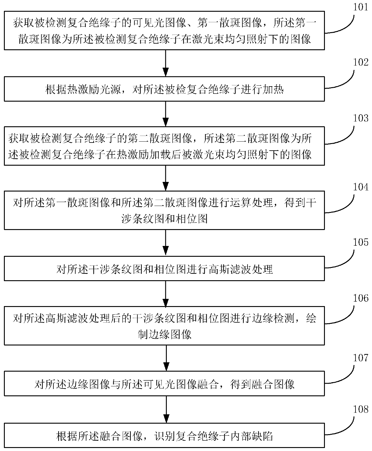
[0055] An embodiment of the present invention provides a detection method for internal bonding defects of composite insulators, which is used in the technical field of power equipment detection. figure 1 Said, the detection method of the internal bonding defect of the composite insulator includes the following steps:

[0056] 101. Acquire a visible light image and a first speckle image of the detected composite insulator, where the first speckle image is an image of the detected composite insulator under uniform laser beam irradiation;

[0057] Specifically, the visible light image is a clear image taken by the detected composite insulator under normal illumination;

[0058] The first speckle image is a dislocation speckle interference image, and the laser beam is uniformly irradiated on the surface of the composite insulator to be detected, and the diffusely reflected single beam dislocation is divided into two beams with the same amplitude, forming two mutual dislocation sca...

Embodiment 2

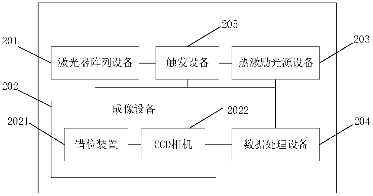
[0108] The embodiment of the present invention provides a detection system for internal bonding defects of composite insulators, which is used in the technical field of power equipment detection. Specifically, it can be used in conjunction with the first embodiment of the present invention to provide a detection method for internal bonding defects of composite insulators. Refer to image 3 As stated, the detection system for internal bonding defects of the composite insulator may include the following structure:

[0109] The laser array device 201 is used to generate a laser beam, which is projected onto the surface of the detected composite insulator through lens expansion;

[0110] Specifically, the emitted light on the surface of the insulator interferes with the reference beam directly projected by the laser array device 201 , thereby generating a speckle field on the irradiated surface of the composite insulator. The laser can control the position of the generated laser b...

Embodiment 3

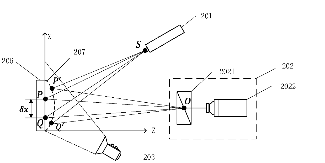
[0127] An embodiment of the present invention provides a detection system for internal bonding defects of composite insulators, which is used in the technical field of power equipment detection, and can be specifically combined with Figure 4 A schematic diagram of a detection system for internal bonding defects of composite insulators is provided to realize the detection and imaging of internal bonding defects of composite insulators.

[0128] The laser array device 201 is used to generate a laser beam, which is projected onto the surface of the detected composite insulator 206 through lens expansion;

[0129] Specifically, the emitted light on the surface of the insulator interferes with the reference beam directly projected by the laser array device 201 , thereby generating a speckle field on the irradiated surface of the composite insulator. The laser can control the position of the generated laser beam in the horizontal and vertical directions, and at the same time adopt ...


PUM


Abstract

The invention discloses a method and a system for detecting bonding defects inside a composite insulator. The method comprises the following steps of acquiring a visible light image, a first speckle image and a second speckle image of a detected composite insulator through laser array equipment, thermal excitation light source equipment, and imaging equipment; performing operation processing on the first speckle image and the second speckle image through the data processing equipment to obtain an interference fringe image and a phase image; and performing Gaussian filtering processing, drawingan edge image to integrate with the visible light image to obtain an integrated image, and identifying bonding defects inside the composite insulator. Through the method disclosed by the invention, the rapid, accurate, non-contact and visual detection of the bonding defects inside the composite insulator is realized, the defection effect on the tiny bonding defects inside the composite insulatoris good, an aim of efficiently and accurately detecting the bonding defects inside the composite insulator is realized; and the method is simple in operation, visual in imaging, the influence by the operation subjective factor of a detector is small, and the objectivity and the scientificity of the detection can be effectively guaranteed.

Description

technical field [0001] The invention relates to the technical field of electric equipment detection, in particular to a detection method and system for internal bonding defects of composite insulators. Background technique [0002] In a complex operating environment, the development of internal defects may cause abnormal heating and insulation failure of the composite insulator, and in severe cases, it may cause breakdown, string drop, breakage and other accidents of the composite insulator, which poses a great threat to the safe and stable operation of the power system . Internal bonding defects of composite insulators are the main cause of accidents such as abnormal heating and fracture of insulators. The detection of internal bonding defects is of great significance to reduce the failure rate of composite insulators. [0003] At present, there are mainly two detection methods for the internal bonding defects of composite insulators. The first one is the anatomical gradi...

Claims


Application Information

Patent Timeline
Patent Type & Authority Applications(China)
IPC IPC(8): G01N21/88G01N21/47G06T7/00G06T7/181
CPCG01N21/8851G01N21/4738G06T7/0008G06T7/181G01N2021/8887G06T2207/20024
Inventor 郭晨鋆涂彦昕舒越刘立帅龚泽威一王黎明马显龙梅红伟段雨廷曹占国
Owner YUNNAN POWER GRID CO LTD ELECTRIC POWER RES INST
Why Eureka
Try Eureka