Oxidation modification system and method for desulfurization ash based on hot flue gas cyclic indirect heating

An oxidation modification and hot flue gas technology, applied in the field of environmental engineering, can solve the problems of high oxidation energy consumption, high oxidation treatment cost of desulfurization waste ash, secondary pollution, etc. The effect of increasing production

Pending Publication Date: 2020-03-06
BEIJING BEIKE ENVIRONMENTAL ENG CO LTD
View PDF4 Cites 2 Cited by
  • Summary
  • Abstract
  • Description
  • Claims
  • Application Information

AI Technical Summary

Problems solved by technology

[0006] In order to solve the problems of high oxidation treatment cost of desulfurization waste ash, secondary pollution and high oxidation energy consumption in the prior art, the present invention provides a system and method for indirect heating of desulfurization ash oxidation modification based on hot flue gas circulation, so that the oxidation treatment Desulfurization ash can be used in cement and gypsum building materials industry to realize resource utilization and high value-added utilization

Method used


Image

  • Oxidation modification system and method for desulfurization ash based on hot flue gas cyclic indirect heating

Examples


Embodiment 1

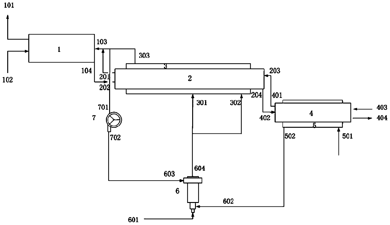
[0037] This embodiment adopts figure 1 The system shown is for oxidation treatment of desulfurization waste ash. In this embodiment, desulfurization waste ash, CaSO 3 The content is 39%, CaSO 4 The content is 15%, and the rest is CaCO 3 , Ca(OH) 2 .

[0038] The specific process is as follows:

[0039] Preheating: The desulfurization waste ash enters the preheating kiln, and the mixed flue gas at 450°C is fed into the kiln tail to heat the material. When it moves to the kiln tail, it can be heated to 150°C, and the residence time in the kiln is 30 minutes.

[0040] Oxidation: The desulfurization waste ash enters the oxidation kiln when the temperature is raised to 150°C, and the hot flue gas with a temperature of 900°C is introduced into the external heating smoke box for indirect heating. , The residence time in the kiln is 30min.

[0041] Cooling: After oxidation, the finished product ash with a temperature of 600°C is sent to the cooling kiln, and is subjected to cou...

Embodiment 2

[0044] This embodiment adopts figure 1 The system shown is for oxidation treatment of desulfurization waste ash. In this embodiment, desulfurization waste ash, CaSO 3 The content is 39%, CaSO 4 The content is 15%, and the rest is CaCO 3 , Ca(OH) 2 .

[0045] The specific process is as follows:

[0046] Preheating: The desulfurization waste ash enters the preheating kiln, and the mixed flue gas at 550°C is fed into the kiln tail to heat the material. When it moves to the kiln tail, it can be heated to 220°C, and the residence time in the kiln is 60 minutes.

[0047] Oxidation: The desulfurization waste ash enters the oxidation kiln when the temperature is raised to 220°C, and the hot flue gas with a temperature of 700°C is introduced into the external heating smoke box for indirect heating. , The residence time in the kiln is 60min.

[0048] Cooling: After oxidation, the finished ash with a temperature of 550°C is sent to the cooling kiln, and is subjected to countercurr...


PUM


Abstract

The invention provides an oxidation modification system and method for desulfurization ash based on hot flue gas cyclic indirect heating, and belongs to the technical field of environmental engineering. The system comprises a rotary pre-heater, an oxidation kiln, an outer heating flue gas box, a rotary cooler, a heat exchanger jacket, a hot air furnace and a high temperature circulating fan. The oxidation kiln is arranged at the rear part of the rotary pre-heater; the outer heating flue gas box is arranged out of the oxidation kiln; heat is supplied to the oxidation kiln by means of hot flue gas; the rotary cooler is arranged at the rear part of the oxidation kiln; cold air is introduced into the rotary cooler for cooling a material; the heat exchange jacket is arranged out of the rotary cooler; the heat exchanger jacket is connected to the hot air furnace; and the hot air furnace is connected to the high temperature circulating fan. The system has the advantages of low energy consumption, high oxidation efficiency, high treatment capacity and the like, and is suitable for industrial production and application.

Description

technical field [0001] The invention relates to the technical field of environmental engineering, in particular to a system and method for indirect heating of desulfurization ash oxidation modification based on hot flue gas circulation. Background technique [0002] With the wide application of semi-dry desulfurization technology, especially in the steel and electric power industries, a large amount of desulfurization waste ash is produced every year in the production process. Desulfurization waste ash is collected from the desulfurization reaction products and unreacted desulfurization absorbent after the reaction between sintering flue gas and calcium-based desulfurizer in the semi-dry flue gas desulfurization process and then separated by cyclone separator, electrostatic precipitator or bag filter. dry powder mixture with flue fly ash. Since desulfurization waste ash contains a large amount of calcium sulfite (CaSO 3 ), the substance has poor stability and slow hydrat...

Claims


Application Information

Patent Timeline
Patent Type & Authority Applications(China)
IPC IPC(8): F27B17/00F27D13/00F27D15/02F27D17/00
CPCF27B17/00F27D13/002F27D15/02F27D17/004F27D2013/007
Inventor 赵荣志陆钢冷廷双员晓孟昭全张秋林杨永毅
Owner BEIJING BEIKE ENVIRONMENTAL ENG CO LTD
Why Eureka
Try Eureka