Method for producing a dry film, rolling device, dry film, and substrate coated with the dry film
A manufacturing method, dry film technology, applied in electrode manufacturing, final product manufacturing, electrode rolling/calendering, etc.
- Summary
- Abstract
- Description
- Claims
- Application Information
AI Technical Summary
Problems solved by technology
Method used
Image

Examples
Embodiment Construction
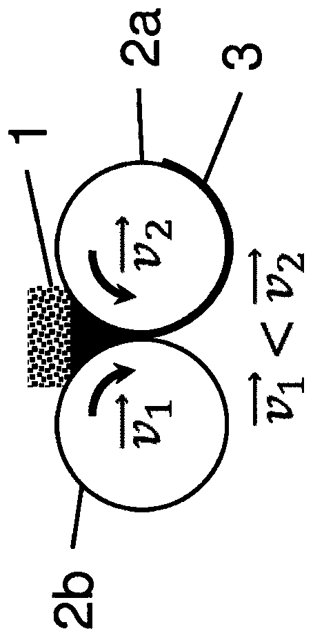
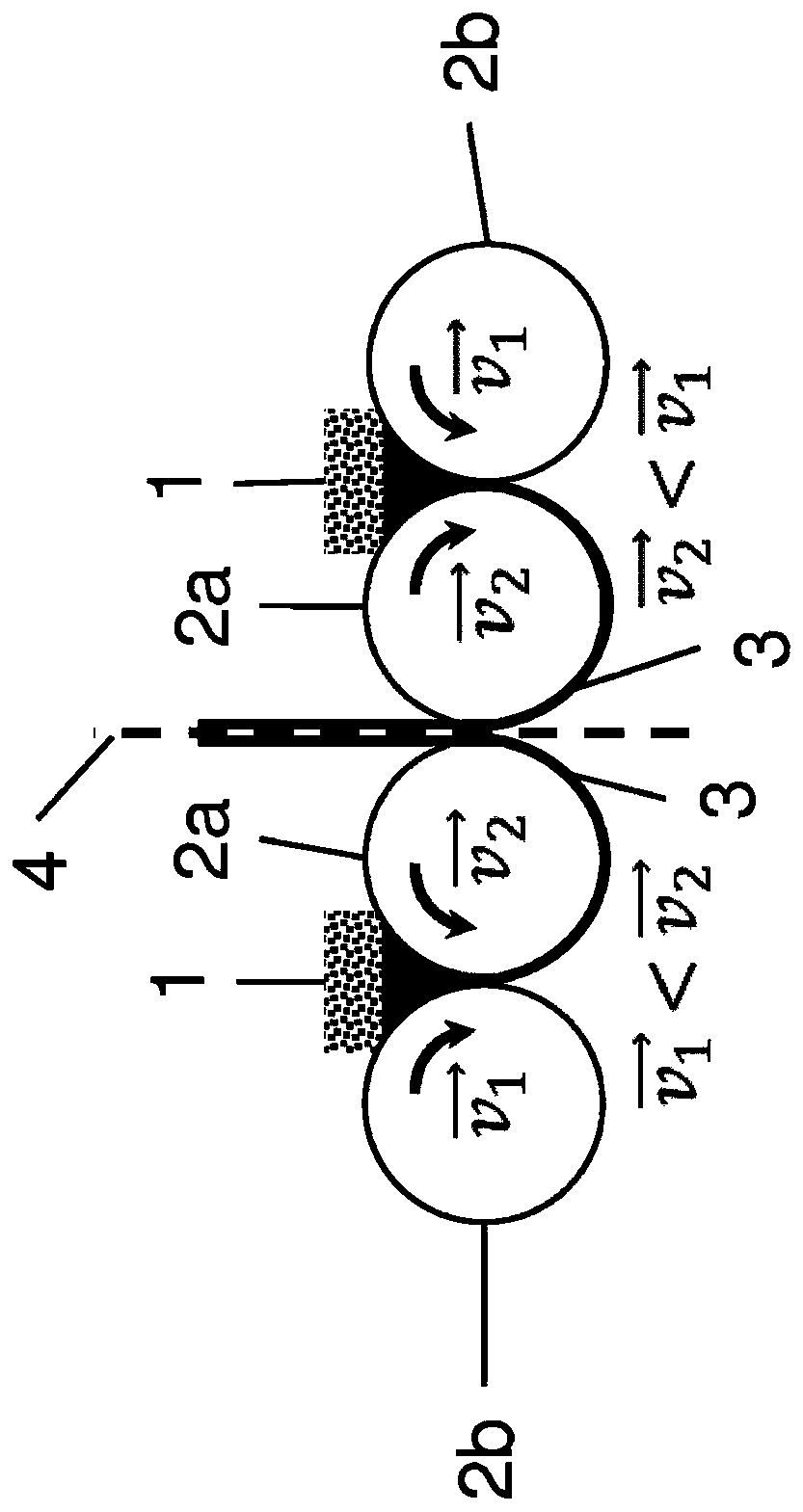
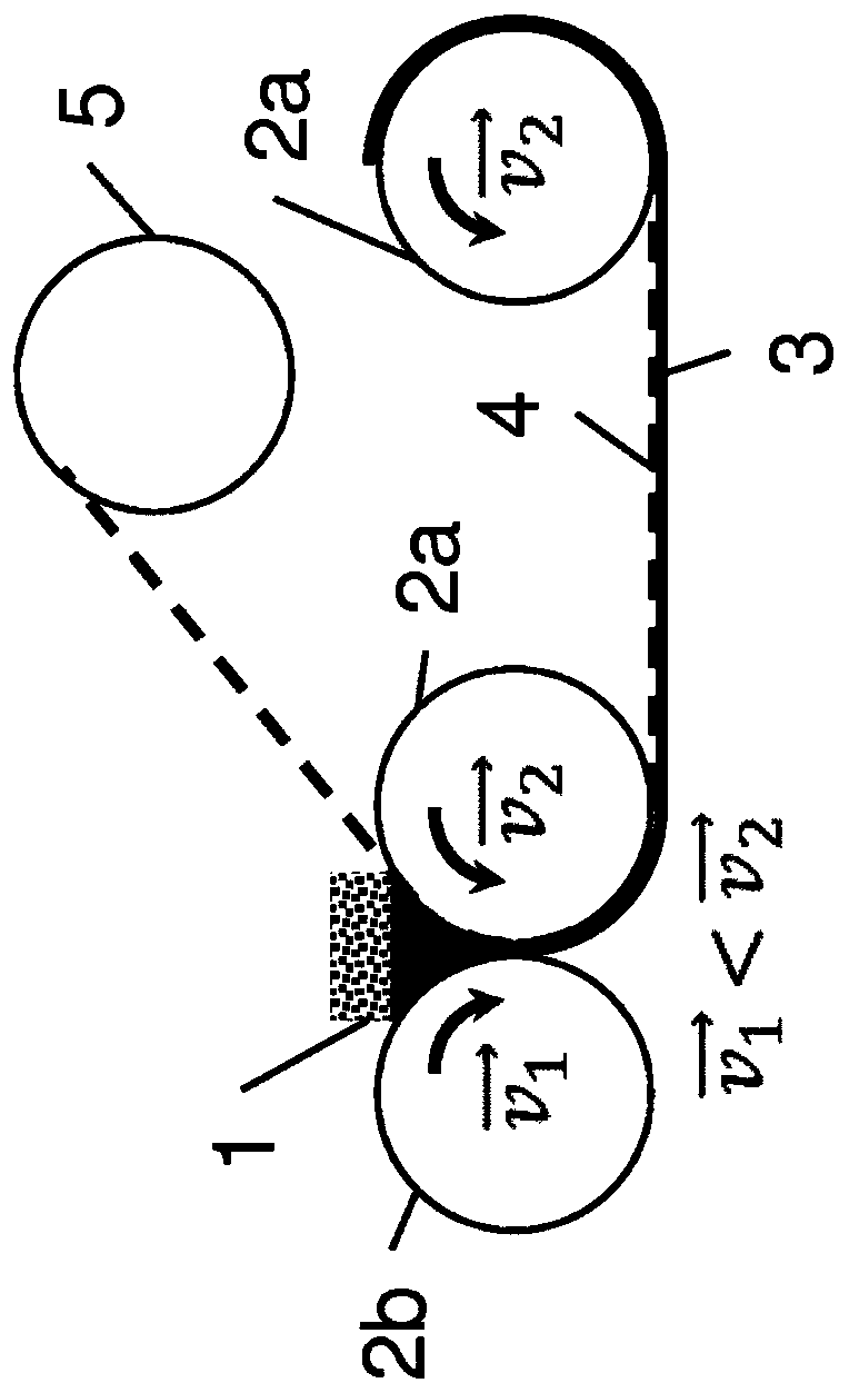
[0037] figure 1 Illustrated is a schematic side view of the roller compaction unit, where, starting from the powder conveyor 1, the dry powder mixture stored in the powder conveyor 1 passes over two chrome-plated calender rollers 2a and 2b of the same size, and through the calender rollers Transition to a stable state by application of pressure and shear. Here, the first calender roll 2a operates at a higher rotational speed than the second calender roll 2b, so that the formed dry film 3 remains on the first calender roll 2a after the combined pressing and shearing operations.
[0038] In the representative example shown, the dry powder used is in a premixed state and contains 90% by weight Ketjen black / sulfur (1:2m / m), 3% by weight polytetrafluoroethylene (PTFE) and 7% by weight % of multi-walled carbon nanotubes (MWCNTs). For Li-ion electrodes, typically 95% by weight lithium manganese oxide, 3% by weight conductive agent (in this case multi-walled carbon nanotubes, MWCNT...
PUM
| Property | Measurement | Unit |
|---|---|---|
| Length | aaaaa | aaaaa |
Abstract
Description
Claims
Application Information