P and S codoped carbon nitride homotype heterojunction composite photocatalyst
A technology of homo-heterojunction and photocatalyst is applied in the field of photocatalytic materials to achieve the effect of improving photocatalytic efficiency, simple preparation method and rapid separation
- Summary
- Abstract
- Description
- Claims
- Application Information
AI Technical Summary
Problems solved by technology
Method used
Image

Examples
Embodiment 1
[0026] Example 1 Synthesis of P, S co-doped g-C 3 N 4 Homogenous junction
[0027] Grind 2g of thiourea, 1g of thiocyanuric acid and 0.2g of hexachlorocyclotriphosphazene (HCCP) into a powder mixture and put it in a covered ceramic crucible. The mixture is calcined at 550°C for 3h, set The heating rate is 8°C min -1 . After the reaction product is cooled to room temperature, it is ground into powder to obtain P, S-codoped homogeneous heterojunction g-C 3 N 4 . The P, S co-doped g-C 3 N 4 Recorded as PSCN.
Embodiment 2
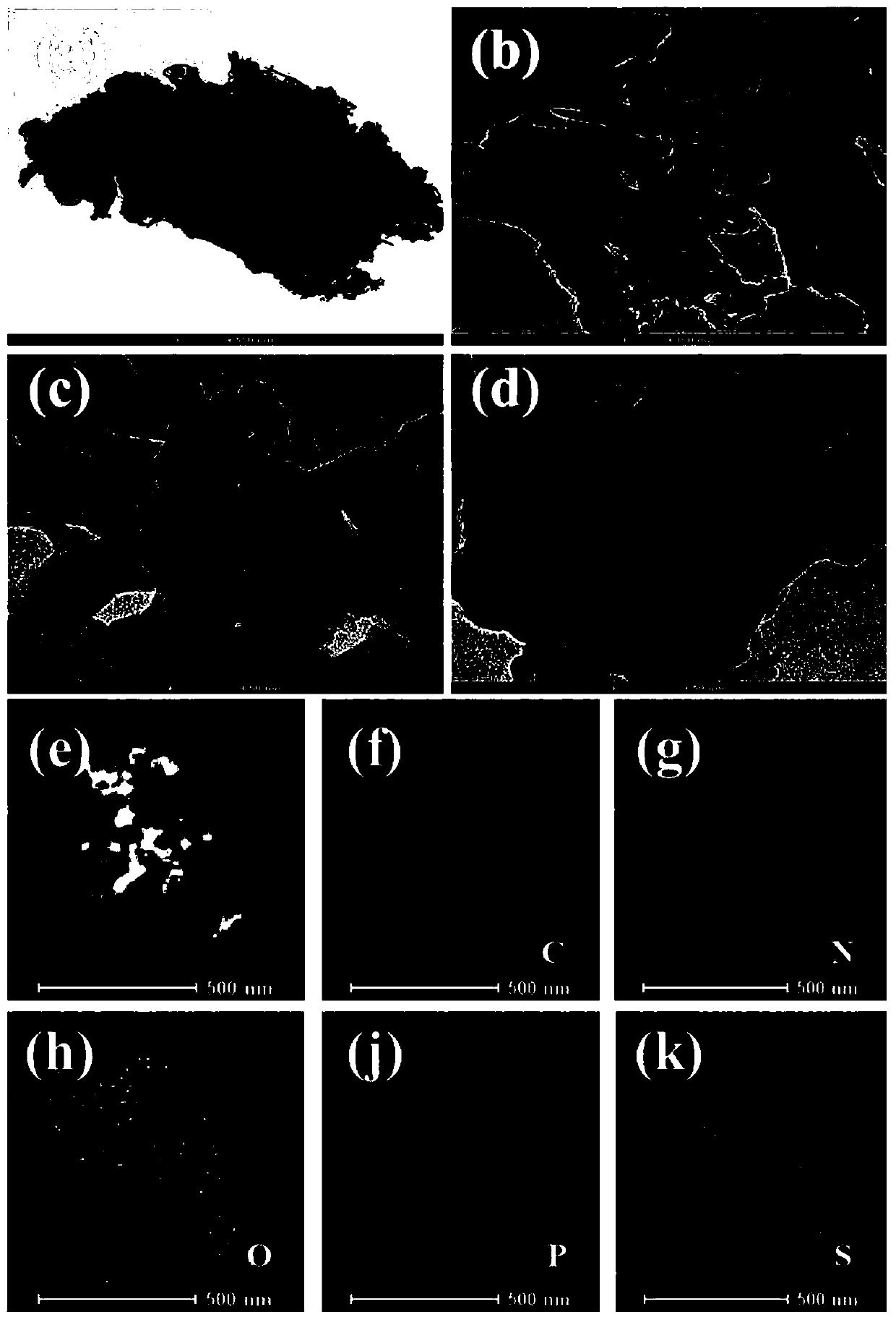
[0034] Embodiment 2 field emission transmission electron microscope (FETEM) test
[0035] Field emission transmission electron microscopy (FETEM) analysis was performed using a Tecnai G2 F30 S-TWIN (FEI, USA) with an accelerating voltage of 300 kV. figure 1 TEM photographs for the elemental maps of SCN-1 and PSCN, from figure 1 It can be seen in (a) that SCN-1 exhibits obvious agglomeration phenomenon, which is due to the uneven heat and mass transfer during thiourea calcination at high temperature. Instead, from figure 1 As can be seen in (b–d), the PSCN has an obvious hierarchical structure and the agglomeration phenomenon is also suppressed. Such as figure 1 (e–k) Shown are the element distribution maps in PSCN samples, and all key elements (C, N, O, P, and S) are uniformly distributed in PSCN in a consistent distribution manner.
Embodiment 3
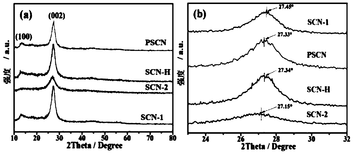
[0036] Embodiment 3 XRD test
[0037] The crystal structures of SCN-1, SCN-2, SCN-H and PSCN were analyzed by X-ray powder diffractometer. figure 2 (a) is the XRD pattern of SCN-1, SCN-2, SCN-H and P, S co-doped homoheterojunction composite (PSCN). From figure 2 As can be seen in (a), SCN-1, SCN-2, SCN-H, and PSCN all show two distinct characteristic diffraction peaks (002) and (100) attributed to graphitic carbonitrides, which indicate that by The structure of the material formed by S doping and the homo-heterojunction composite material formed by copolymerization did not change significantly. At the same time, it can be observed that the structure of SCN-2 obtained only by calcining thiocyanuric acid has obvious structural defects, and the diffraction peak of the 110 crystal plane almost disappears. according to figure 2 (b) It can be seen that the amplified (002) diffraction peaks of PSCN and SCN-H (PSCN, 27.33°; SCN-H, 27.34°) are located between SCN-1 and SCN-2, in...
PUM
 Abstract
Description
Claims
Application Information
 - R&D
- Intellectual Property
- Life Sciences
- Materials
- Tech Scout
- Unparalleled Data Quality
- Higher Quality Content
- 60% Fewer Hallucinations
Browse by: Latest US Patents, China's latest patents, Technical Efficacy Thesaurus, Application Domain, Technology Topic, Popular Technical Reports.
© 2025 PatSnap. All rights reserved.Legal|Privacy policy|Modern Slavery Act Transparency Statement|Sitemap|About US| Contact US: help@patsnap.com