Spectroscopy and Imaging Optical System of Surface Plasmon Resonance in Invisible Light Band

A surface plasmon and imaging optics technology, applied in the field of spectrum measurement and imaging optical system, can solve the problems of high cost, high optical resolution, complex structure, etc., and achieve the effect of reducing workload and cost

Active Publication Date: 2022-01-11
WESTLAKE UNIV
View PDF0 Cites 0 Cited by
  • Summary
  • Abstract
  • Description
  • Claims
  • Application Information

AI Technical Summary

Problems solved by technology

The advantages of using bright-field or dark-field scattering optical microscopy are high optical resolution, but the disadvantages are high cost, complex structure, and surface plasmon resonance that can only be characterized in the visible light band

Method used


Image

  • Spectroscopy and Imaging Optical System of Surface Plasmon Resonance in Invisible Light Band
  • Spectroscopy and Imaging Optical System of Surface Plasmon Resonance in Invisible Light Band
  • Spectroscopy and Imaging Optical System of Surface Plasmon Resonance in Invisible Light Band

Examples


Embodiment 1

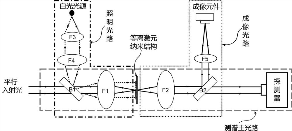
[0021] Example 1: as Figure 1~Figure 8 As shown, a spectrum measurement and imaging optical system for surface plasmon resonance in the invisible light band includes a laser, an object stage, a measured plasmon nanostructure, a main spectrum measurement optical path, an imaging optical path and an illumination optical path.

[0022] The laser is a laser in the visible light band, which is used to determine the image of the main optical path focus in the imaging optical path.

[0023] The stage is a two-dimensional or three-dimensional movable stage on which samples with plasmonic nanostructures can be fixed. The stage is located at the confocal position of two confocal condensing optical elements in the main optical path of the spectrum measurement, and confocalness is the coincidence of the focal points of the two confocal optical elements.

[0024] The main optical path for spectrum measurement includes two confocal condensing optical elements F1 and F2, two spectral optic...

Embodiment 2

[0045] Figure 1-4 The four optical paths are equivalent in figure 1 The illustrated embodiments illustrate two preferred embodiments of spectral main path signal collection.

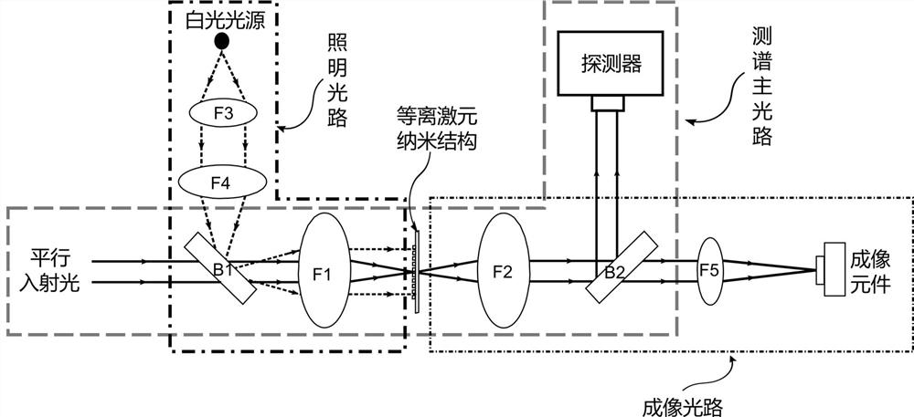
[0046] Option 1: If the photodetector with dispersion function has an optical fiber input interface, along the beam propagation direction, use a collimator to couple the transmitted light signal into the optical fiber at a position behind the splitting optical element B2 in the main optical path of the spectrum measurement. like Figure 5 shown. The working wavelength of the collimating mirror matches the working wavelength of the invisible light band light source and the photodetector, and the NA value of the collimating mirror matches the NA value of the optical fiber. The collimating mirror can effectively collect the transmitted parallel light signal and provide a switching function for free-space light coupling into the optical fiber.

[0047] Option 2: If the photodetector with dispersion func...

Embodiment 3

[0049] Figure 1-4 The four optical paths are equivalent in figure 1 The illustrated embodiment illustrates a preferred embodiment of the spectroscopic main optical path signal input.

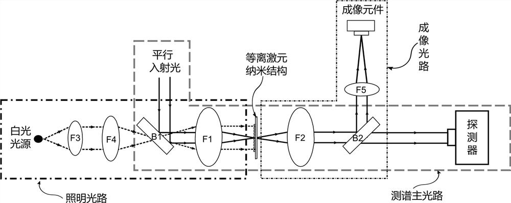
[0050] If the invisible light band light source has an optical fiber output interface, a collimator should be placed at a certain position in front of the splitting optical element B1 in the main optical path of the spectrum measurement along the propagation direction of the light beam. The collimator is coupled with the optical fiber to output the light source signal in the invisible light band as parallel light, such as Figure 7 shown. The working wavelength of the collimating mirror matches the working wavelength of the invisible light source, and the NA value of the collimating mirror matches the NA value of the optical fiber. The collimating mirror can effectively collect the optical signal in the optical fiber, and provide an effective way for the optical signal in the optical fiber t...


PUM


Abstract

The invention relates to a spectrum measurement and imaging optical system of surface plasmon resonance in the invisible light band, including a laser, an object stage, a plasmon nanostructure to be measured, a spectrum measurement main optical path, an imaging optical path and an illumination optical path. In practical applications, it is only necessary to measure the transmitted light signal of the focus of the main optical path of the spectrum within and outside the region of the plasmonic nanostructure to be measured, and the peak of the surface plasmon resonance corresponding to the nanostructure can be quickly obtained The position and full width at half maximum greatly simplify the workload of characterizing the optical properties of surface plasmon resonances, and provide an effective basis for the design and application of plasmonic nanostructures.

Description

technical field [0001] The invention designs a micro-nano photon spectrum measurement and imaging optical system, in particular to a spectrum measurement and imaging optical system with surface plasmon resonance in the invisible light band. Background technique [0002] Surface plasmon resonance is an electromagnetic oscillation formed during the interaction between light and plasmonic nanostructures. It can break through the diffraction limit and achieve localized electromagnetic field enhancement. , organic solar cells and other fields have been widely used. Optical characterization of surface plasmon resonance, such as the wavelength position of the resonance peak, the full width at half maximum of the resonance peak, etc., is the premise to make full use of the resonance effect. Theoretically, the optical characterization of surface plasmon resonances can utilize both the absorption and scattering spectra of plasmonic nanostructures, as well as their extinction spectra....

Claims


Application Information

Patent Timeline
Patent Type & Authority Patents(China)
IPC IPC(8): G01N21/25G01N21/21G01J3/28
CPCG01N21/25G01N21/21G01J3/2823G01N2021/258G01N2021/217
Inventor 王纪永仇旻
Owner WESTLAKE UNIV
Why Eureka
Try Eureka