
A kind of method for preparing optical fiber cladding optical filter based on electroless Cu plating method

A fiber cladding and electroless plating technology, applied in the laser field, can solve problems such as limiting the performance of the cladding light filter, difficulty in stabilizing the cladding light filtering, and high temperature of the light guide glue, so as to achieve process optimization and good coating quality , to overcome the effect of uneven temperature

Active Publication Date: 2021-03-30
NAT INNOVATION INST OF DEFENSE TECH PLA ACAD OF MILITARY SCI
View PDF5 Cites 0 Cited by
  • Summary
  • Abstract
  • Description
  • Claims
  • Application Information

AI Technical Summary

Problems solved by technology

However, in practical applications, when the optical power of the filter prepared by this method is high, the temperature of the light-guiding glue on the surface of the optical fiber cladding will be too high, and the phenomenon of burning will occur.
Some scholars use the hydrofluoric acid segmental etching method to strip the cladding light. However, in the application, due to the change of the cladding structure, a large amount of light will leak at the front end of the filter, and hot spots will be formed locally, which is difficult to stabilize. The cladding light is filtered out, which greatly limits the performance improvement of the cladding light filter

Method used


Image

  • A kind of method for preparing optical fiber cladding optical filter based on electroless Cu plating method
  • A kind of method for preparing optical fiber cladding optical filter based on electroless Cu plating method
  • A kind of method for preparing optical fiber cladding optical filter based on electroless Cu plating method

Examples


Embodiment 1

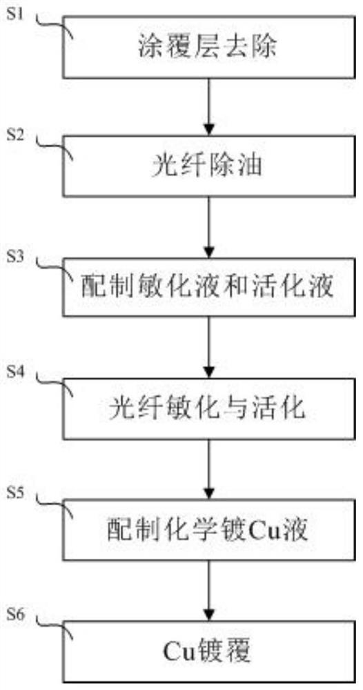
[0039] as per figure 1 The process flow shown prepares the optical fiber cladding optical filter, and the specific steps are as follows:

[0040] S1. Take an optical fiber with a length of 2m, soak a 20cm-long section of the middle part of the optical fiber in acetone for 15min, and then wash it with concentrated H 2 SO 4 Soak for 1 minute to remove the coating layer, and then wash it once with 95% alcohol to obtain a section of optical fiber from which the coating layer has been removed;

[0041] S2: Optical fiber degreasing: Remove the coated optical fiber from this section and soak it in 40g / L NaOH solution for 15 minutes to degrease and decontaminate. Finally, wash it once with 95% alcohol and dry it for later use;

[0042] S3. Prepare sensitization solution and activation solution, the composition of sensitization solution is SnCl 2 15g / L, 37% HCl 30ml / L, the activation solution is PdCl 2 0.5g / L, 37% HCl 5ml / L, heat the sensitizing solution to 25°C, and heat the act...

Embodiment 2

[0050] Embodiment 2 Performance detection of optical fiber cladding optical filter

[0051] The optical fiber with the optical fiber cladding optical filter prepared in embodiment 1 and the 200W LD pumping light source and the 7×1 beam combiner device are as follows image 3 For the connection shown, use a 300W power meter to detect the output power of the laser after being processed by the fiber cladding optical filter. During the test, the laser light generated by the LD is coupled by the beam combiner device, enters the optical fiber with the optical fiber cladding filter, and finally enters the power meter. During the test, the surface temperature of the electroless Cu-plated optical fiber was monitored by an infrared thermal imager. When the test was selected when the surface temperature was 100°C, the passing power of the electroless Cu-plated optical fiber was recorded, and the pumping light transmission rate of the electroless Cu-plated optical fiber was calculated. J...


PUM

PropertyMeasurementUnit
lengthaaaaaaaaaa
melting pointaaaaaaaaaa

Abstract

The invention provides a method for preparing an optical fiber cladding light filter based on a chemical Cu plating method. According to the method, a metal Cu plating layer is prepared on the surfaceof an optical fiber with a coating layer removed by using a chemical Cu plating technology, and the chemical plating Cu solution mainly comprises 40-50 g of sodium potassium tartrate, 10-15 g of copper sulfate pentahydrate, 1-2 g of nickel sulfate, 20-25 ml of formaldehyde, 1-2 g of sodium carbonate and a proper amount of stabilizer. The prepared metal Cu plating layer is good in quality and is uniformly deposited on the surface of the coating layer removed optical fiber, and the metal Cu is a good conductor in nature, so that according to the method provided by the invention, the problem that the cladding light of the traditional cladding light filter leaks a lot, so that the local temperature rises quickly and is burnt out is solved, the overall temperature distribution of the claddinglight filter is uniform, and meanwhile, the cladding light can be stripped uniformly.

Description

technical field [0001] The invention belongs to the technical field of lasers, and relates to a method for an optical fiber cladding optical filter, in particular to a method for preparing an optical fiber cladding optical filter based on an electroless Cu plating method. Background technique [0002] With the wide application of laser technology in the industrial field, the power of lasers is also increasing. At the same time, higher requirements are put forward for the laser beam quality and the stability of the system. For high-power output fiber lasers, too long gain fibers cannot be prepared due to nonlinear effects, resulting in a part of the pump light remaining in the inner cladding of the fiber, and as the output power of the laser increases, the remaining pump light power will also increase; At the same time, due to the fusion and bending of the optical fiber, some signal light will leak into the inner cladding of the optical fiber. If the residual light is transm...

Claims


Application Information

Patent Timeline
Patent Type & Authority Patents(China)
IPC IPC(8): H01S3/067C23C18/18C23C18/40
CPCC23C18/1893C23C18/405H01S3/067
Inventor 胡振峰宋启良梁秀兵孔令超金国刘二宝涂龙崔辛陈永雄罗晓亮王浩旭胡海韵王荣
Owner NAT INNOVATION INST OF DEFENSE TECH PLA ACAD OF MILITARY SCI
Learn More