
Stirring type environment-friendly electroplating wastewater precipitation treatment device

A technology for electroplating wastewater and sedimentation treatment, which is applied in the fields of metallurgical wastewater treatment, flocculation/sedimentation water/sewage treatment, water/sewage treatment, etc. High-efficiency mixing, increased precipitation processing capacity, and high reliability

Inactive Publication Date: 2020-04-07
陶李
View PDF1 Cites 2 Cited by
  • Summary
  • Abstract
  • Description
  • Claims
  • Application Information

AI Technical Summary

Problems solved by technology

Due to many types of plating, cumbersome process, complex water quality, and difficult control of components, electroplating wastewater mainly contains heavy metal ions such as chromium, cadmium, nickel, copper, zinc, gold, silver and cyanide, etc. These electroplating wastewater are carcinogenic and teratogenic , Mutagenic and highly toxic substances have caused great harm to the living environment of humans and other organisms
[0004] The existing electroplating wastewater treatment methods usually include flocculation treatment, precipitation treatment and solid-liquid separation treatment; while the existing equipment or devices suitable for the above methods have poor treatment effect and low treatment efficiency, especially stirring and sedimentation are easy to conflict and affect each other , affecting the precipitation effect, the practicability is not strong
[0005] Chinese patent (notification number: CN207330460U) discloses a sedimentation treatment device for electroplating wastewater, which includes a pool with an open upper end and a cover on the pool; The plate separates it into a flocculation tank and a sedimentation separation tank; the flocculation tank and the sedimentation separation tank are communicated through a solenoid valve located on the partition; a stirrer is provided in the flocculation tank; the stirrer includes a stirring motor, A stirring rod arranged on the rotating shaft of the stirring motor and a stirring blade arranged at the end of the stirring rod; the stirring motor is arranged on the cover, and the upper end of the stirring rod penetrates the cover to the In addition to the above-mentioned flocculation tank, although the device can realize the automatic lifting of the agitator to a certain extent, and it is convenient to adjust the height of the agitator according to the liquid depth in the flocculation tank, but in actual operation, the flocculant cannot be adjusted according to the hydraulic depth. Reasonable liquid intake, so that a large amount of flocculant is located in the liquid layer and cannot reach the sedimentation layer, therefore, the above-mentioned device still needs further improvement

Method used


Image

  • Stirring type environment-friendly electroplating wastewater precipitation treatment device
  • Stirring type environment-friendly electroplating wastewater precipitation treatment device
  • Stirring type environment-friendly electroplating wastewater precipitation treatment device

Examples


Embodiment 1

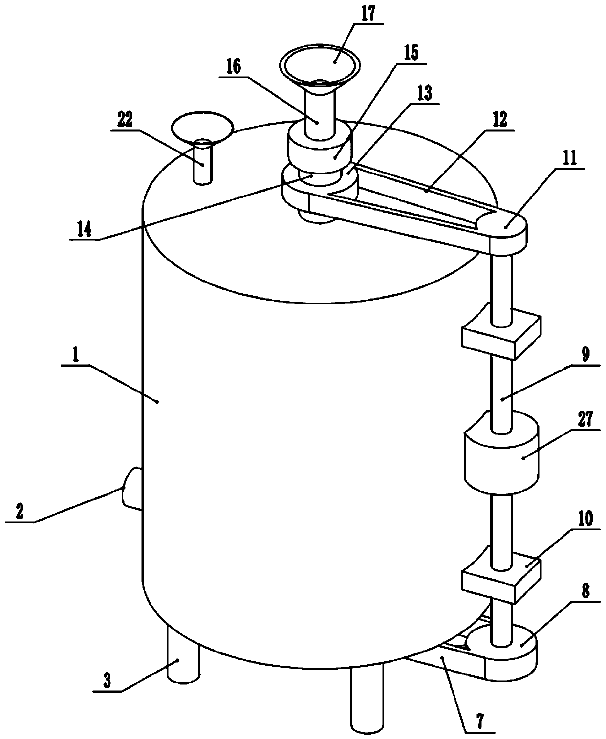
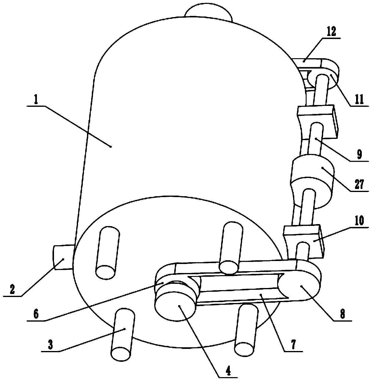
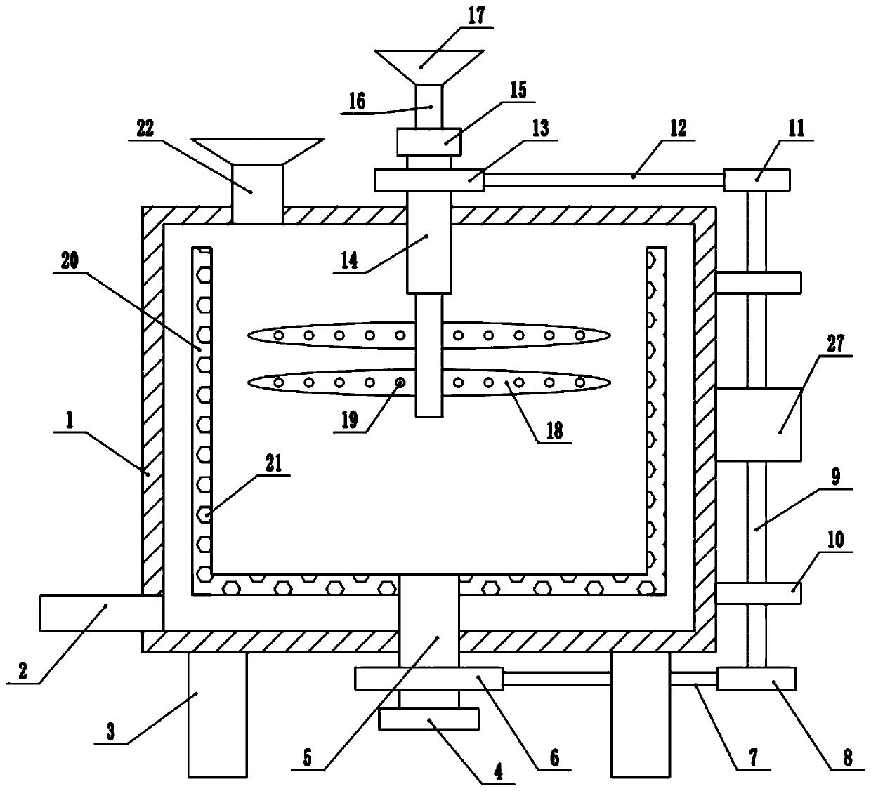
[0033] refer to Figure 1-7, in an embodiment of the present invention, a stirring environment-friendly electroplating wastewater precipitation treatment device includes a stirring box 1, and a drain pipe 2 is installed at the lower left side of the stirring box 1 for the non-precipitating liquid layer generated during the precipitation process The liquid in the mixing box 1 is discharged, and the four corners of the bottom of the mixing box 1 are equipped with support legs 3, which are used to support and fix the mixing box 1. The inside of the mixing box 1 is equipped with an isolation cylinder 20, and the inner wall of the isolation cylinder 20 is uniformly provided with a number of discharge holes. 21. By setting discharge holes 21 on the isolation cylinder 20, the water attached to the sediment inside the isolation cylinder 20 can be quickly discharged under the action of centrifugal force. The bottom end of the isolation cylinder 20 is equipped with a rotating shaft 5, an...

Embodiment 2

[0035] In another embodiment of the present invention, the difference between this embodiment and the above-mentioned embodiment is that the upper end of the stirring box 1 is installed on the left side and a feed hopper 22 is also installed for the introduction of electroplating waste water. By setting the feed hopper 22 can separate the electroplating waste water and the flocculant into the introduction channel inside the stirring tank 1, avoiding precipitation on the inner wall of the feeding hopper 17, and increasing the reliability of the whole device.

[0036] In the present invention, when in use, electroplating wastewater and flocculants are introduced into the inside of the stirring tank 1 through the feed hopper 22 and the feeding hopper 17, and then the biaxial motor 27 is started to make the stirring shaft 16 and the rotating shaft 5 rotate accordingly, so that The internal electroplating wastewater can be precipitated and stirred. During this process, we can adjust...


PUM


Abstract

The invention relates to the technical field of environment-friendly treatment equipment, and discloses a stirring type environment-friendly electroplating wastewater precipitation treatment device which comprises a stirring box, an isolation cylinder is installed in the stirring box, a rotating shaft is installed at the bottom end of the isolation cylinder, and the bottom end of the rotating shaft penetrates through the middle of the bottom end of the stirring box to be connected with a first belt wheel. The inner part of the rotating shaft is an empty shaft and is communicated with the innerpart of the isolation cylinder. The right end of the first belt wheel is connected with a second belt wheel through a first belt, the upper end of the second belt wheel is connected with an output shaft at the lower end of a double-shaft motor, the output shaft at the upper end of the double-shaft motor is connected with a third belt wheel, the left side of the third belt wheel is connected witha third belt wheel through a second belt, and a driving shaft is installed in the middle of the third belt wheel; a hollow shaft is arranged in the driving shaft, and a stirring shaft is arranged in the driving shaft. According to the electroplating wastewater treatment device, the isolation cylinder and the stirring shaft rotate, the efficient mixing effect of an internal flocculant and electroplating wastewater is improved, meanwhile, the vertical height of stirring blades can be adjusted, and the stirring requirements of different heights are met.

Description

technical field [0001] The invention relates to the technical field of environmental protection treatment equipment, in particular to a stirring type environmental protection electroplating wastewater precipitation treatment device. Background technique [0002] Electroplating is the process of plating a thin layer of other metals or alloys on the surface of certain metals using the principle of electrolysis. It is a process of using electrolysis to attach a layer of metal film to the surface of metal or other material parts to prevent metal oxidation ( Such as rust), improve wear resistance, electrical conductivity, reflective properties, corrosion resistance (copper sulfate, etc.) and enhance the appearance. The outer layer of many coins is also electroplated. [0003] At present, electroplating wastewater is mainly composed of wastewater and waste liquid discharged from electroplating factories (or workshops), such as rinsing water for plated parts, waste bath liquid, eq...

Claims


Application Information

Patent Timeline
IPC IPC(8): C02F1/52C02F103/16
CPCC02F1/52C02F2103/16C02F2201/002
Inventor 陶李
Owner 陶李
Learn More