Wet denitration process
A wet denitrification and process technology, applied in the field of wet denitrification process, can solve the problems of cost increase
- Summary
- Abstract
- Description
- Claims
- Application Information
AI Technical Summary
Problems solved by technology
Method used
Image

Examples
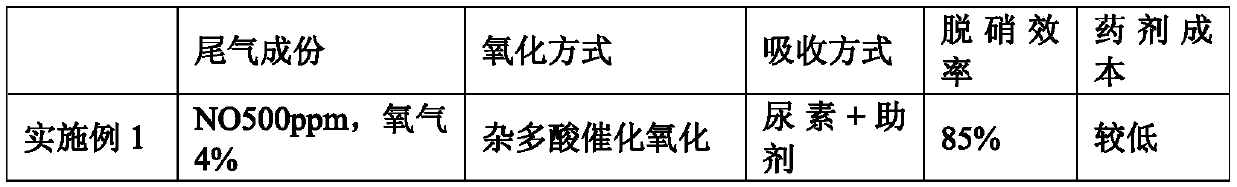
Embodiment 1
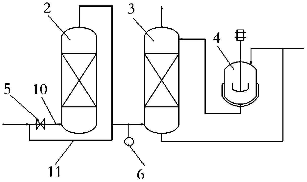
[0027]The waste gas (containing NO500ppm, oxygen 4%) after dedusting and desulfurization is input into the oxidizer from the lower part through the first conveying pipe. At 90°C, a part of the oxidized exhaust gas and another part of the unoxidized exhaust gas enter a scrubber together. The monitoring instrument at the gas inlet of the scrubber is linked with the electric intake valve to adjust the flow of exhaust gas entering the oxidizer in real time. When the monitoring instrument detects NO and NO 2 When the molar ratio is less than 1:1, the feedback signal is sent to the electric intake valve to increase the flow of exhaust gas entering the oxidizer; when the monitoring instrument detects NO and NO 2 When the molar ratio is greater than 1:1, the feedback signal is sent to the electric intake valve, and the exhaust gas flow into the oxidizer is reduced or closed; the mass percentage concentration is added to a dispenser: 15% urea, 0.10% EDTA, 0.05% Triethanolamine, 0.05% ...
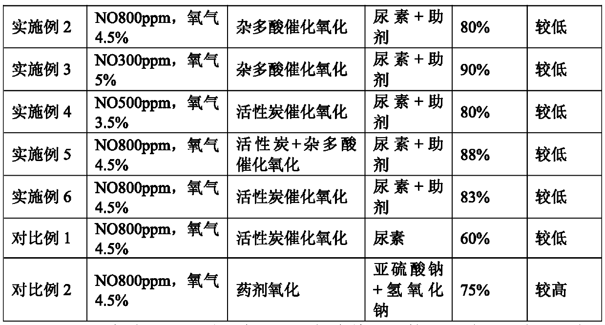
Embodiment 2
[0029] The waste gas (containing NO800ppm, oxygen 4.5%) after dedusting and desulfurization is input into the oxidizer from the lower part through the first conveying pipe. At 85°C, a part of the oxidized waste gas and another part of the unoxidized waste gas enter a scrubber together. The monitoring instrument at the gas inlet of the scrubber is linked with the electric intake valve to adjust the flow of the exhaust gas entering the oxidizer in real time. When the monitoring instrument detects NO and NO 2 When the molar ratio is less than 1:1, the feedback signal is sent to the electric intake valve to increase the flow of exhaust gas entering the oxidizer; when the monitoring instrument detects NO and NO 2 When the molar ratio is greater than 1:1, the feedback signal is sent to the electric intake valve, and the exhaust gas flow into the oxidizer is reduced or closed; the mass percentage concentration is added to a dispenser: 10% urea, 0.08% ethylenediamine Cobalt, 0.08% of...
Embodiment 3
[0031] The waste gas (containing NO300ppm, oxygen 5%) after dedusting and desulfurization is input into the oxidizer from the lower part through the first conveying pipe. At 90°C, a part of the oxidized exhaust gas and another part of the unoxidized exhaust gas enter a scrubber together. The monitoring instrument at the gas inlet of the scrubber is linked with the electric intake valve to adjust the flow of exhaust gas entering the oxidizer in real time. When the monitoring instrument detects NO and NO 2 When the molar ratio is less than 1:1, the feedback signal is sent to the electric intake valve to increase the flow of exhaust gas entering the oxidizer; when the monitoring instrument detects NO and NO 2 When the molar ratio is greater than 1:1, the feedback signal is sent to the electric intake valve, and the exhaust gas flow into the oxidizer is reduced or closed; the mass percentage concentration is added to a dispenser: 20% urea, 0.20% EDTA ferrous, 0.06% of triethanola...
PUM
 Abstract
Description
Claims
Application Information
 - R&D Engineer
- R&D Manager
- IP Professional
- Industry Leading Data Capabilities
- Powerful AI technology
- Patent DNA Extraction
Browse by: Latest US Patents, China's latest patents, Technical Efficacy Thesaurus, Application Domain, Technology Topic.
© 2024 PatSnap. All rights reserved.Legal|Privacy policy|Modern Slavery Act Transparency Statement|Sitemap