Metal wire grating polarizer with deep ultraviolet composite structure

A composite structure and metal wire grid technology, which is applied in polarizing components, instruments, optics, etc., can solve the problems of not considering the stability of polarization performance, high polarization transmittance and extinction ratio, and strict grating period restrictions, so as to meet the requirements of Performance requirements, reduction of processing difficulty and cost, effect of long cycle

Active Publication Date: 2020-04-17
SHANGHAI INST OF OPTICS & FINE MECHANICS CHINESE ACAD OF SCI
View PDF8 Cites 1 Cited by
  • Summary
  • Abstract
  • Description
  • Claims
  • Application Information

AI Technical Summary

Problems solved by technology

The wire grid polarizer used in the ultraviolet band in the above article often cannot take into account the high extinction ratio and the large grating period. The extinction ratio is often improved by reducing the characteristic size of the wire grid so that the grating only generates zero-order diffracted light, and the affected The limitation of nanotechnology makes the processing difficulty greatly increased
[0004] The common problem with the above wire grid polarizers used in the deep ultraviolet band is that they usually only use the zero-order diffraction of the grating, and obtain higher polarization transmittance and extinction ratio by constraining the grating period to be much smaller than the incident wavelength
For the deep ultraviolet band, the restriction conditions of the grating period are more stringent, the small grating period makes the processing difficult and the production cost is high, and most studies only consider the case of vertical incidence, and do not consider the stability of the polarization performance in the case of large-angle incidence

Method used


Image

  • Metal wire grating polarizer with deep ultraviolet composite structure
  • Metal wire grating polarizer with deep ultraviolet composite structure
  • Metal wire grating polarizer with deep ultraviolet composite structure

Examples


Embodiment 1

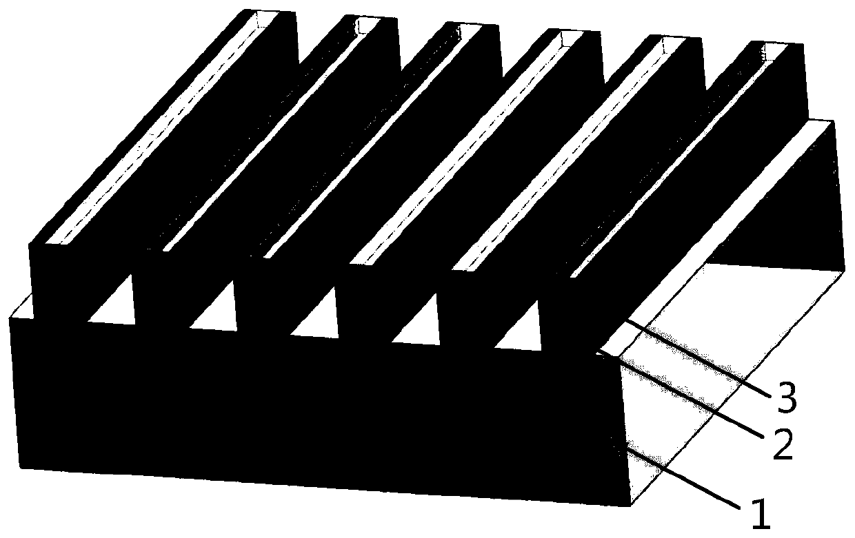
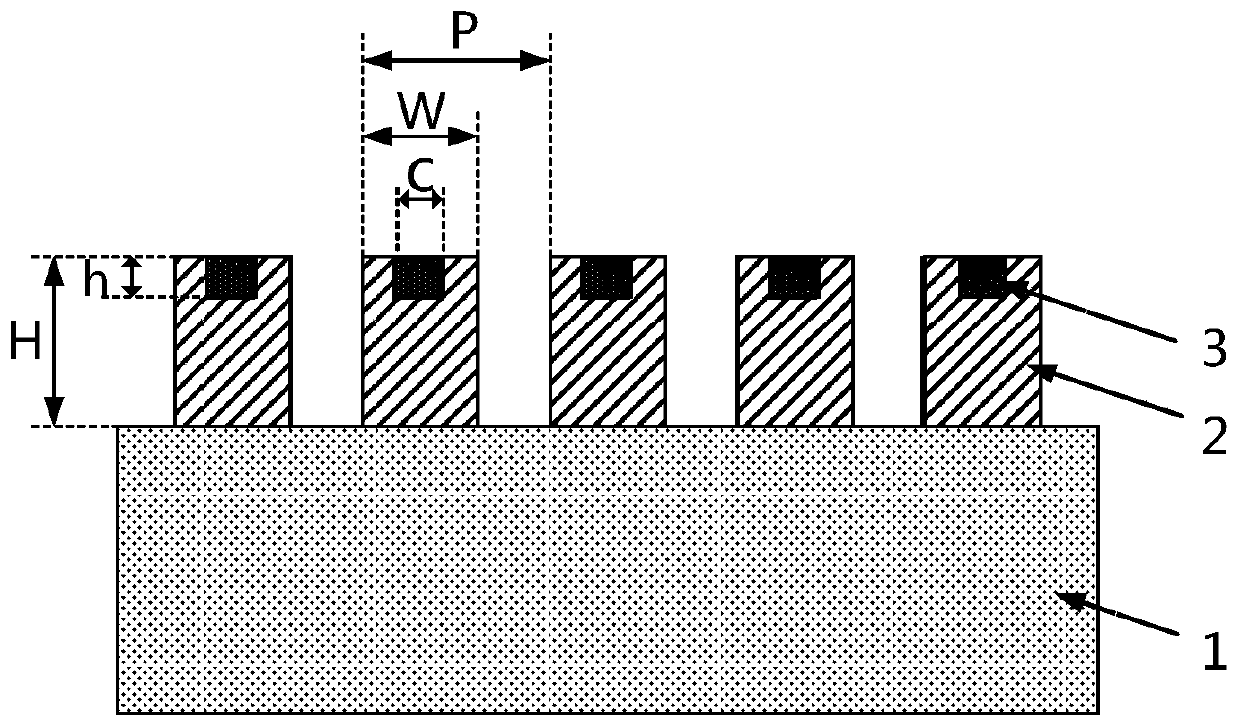
[0027] The metal aluminum grating and the magnesium fluoride dielectric filling structure have the same period P of 134nm, aluminum grid duty ratio W / P of 0.67, and aspect ratio H / W of 2.5. The width of the rectangular magnesium fluoride dielectric filled structure is 32 nm, and the depth is 15 nm.

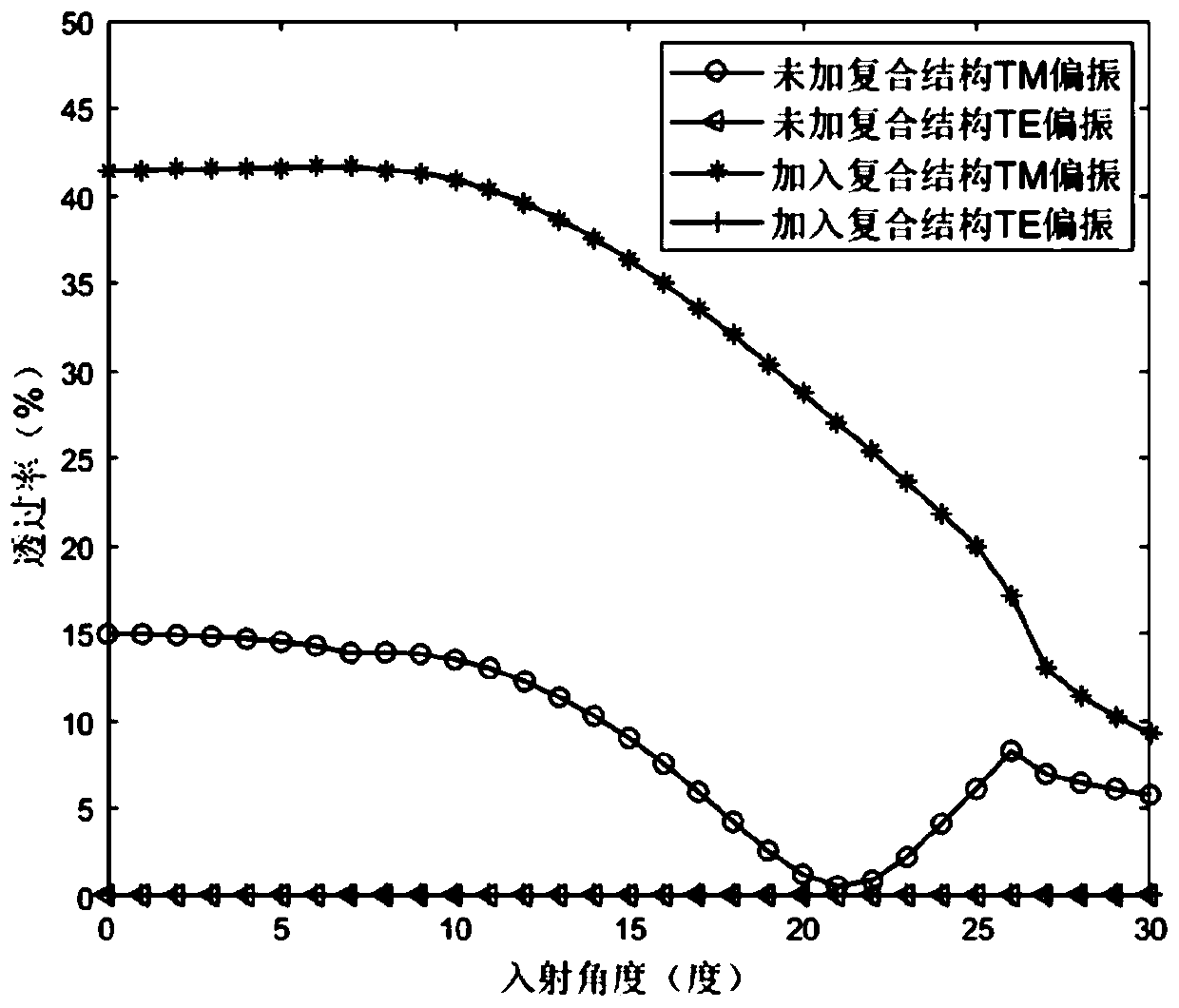
[0028] see image 3 , image 3 It is a graph of the transmittance of TM polarized light and TE polarized light of embodiment 1 with the incident angle. Among them, the o line type represents the TM polarized light transmittance without a composite structure wire grid polarizer, the Δ line type represents the TE polarized light transmittance without a composite structure wire grid polarizer, and the * line type represents without a composite structure wire grid Polarizer TM polarized light transmittance, + line means TE polarized light transmittance without compound structure wire grid polarizer. Depend on image 3 It can be seen that at normal incidence, the polarized light tr...

Embodiment 2

[0031] The metal aluminum grating and the silicon dioxide dielectric filling structure have the same period P of 176nm, aluminum grid duty ratio W / P of 0.74, and aspect ratio H / W of 3. The width of the rectangular silicon dioxide dielectric filled structure is 84nm, and the depth is 60nm.

[0032] see Figure 5 , Figure 5 It is a graph of the transmittance of TM polarized light and TE polarized light of embodiment 2 with the incident angle. Among them, the o line type represents the TM polarized light transmittance without a composite structure wire grid polarizer, the Δ line type represents the TE polarized light transmittance without a composite structure wire grid polarizer, and the * line type represents without a composite structure wire grid Polarizer TM polarized light transmittance, + line means TE polarized light transmittance without compound structure wire grid polarizer. Depend on Figure 5It can be seen that at normal incidence, the transmittance of the polar...

Embodiment 3

[0035] The metal aluminum grating and the silicon dioxide dielectric filling structure have the same period P of 200nm, aluminum grid duty ratio W / P of 0.76, and aspect ratio H / W of 1.52. The width of the rectangular silicon dioxide dielectric filling structure is 80 nm, and the depth is 30 nm.

[0036] see Figure 7 , Figure 7 It is a graph of the transmittance of TM polarized light and TE polarized light of embodiment 3 with the incident angle. Among them, the o line type represents the TM polarized light transmittance without a composite structure wire grid polarizer, the Δ line type represents the TE polarized light transmittance without a composite structure wire grid polarizer, and the * line type represents without a composite structure wire grid Polarizer TM polarized light transmittance, + line means TE polarized light transmittance without compound structure wire grid polarizer. Depend on Figure 7 It can be seen that at normal incidence, the polarized light tra...


PUM

PropertyMeasurementUnit
wavelengthaaaaaaaaaa
widthaaaaaaaaaa
depthaaaaaaaaaa

Abstract

The invention discloses a metal wire grating polarizer with a deep ultraviolet composite structure. The metal wire grating polarizer comprises a substrate, a metal grating with a groove and a medium filling structure, wherein the metal grating and the medium filling structure have the same period P of 100-300nm, the duty ratio W/P of the metal grating is 0.5-0.85, and the height-width ratio H/W ofthe metal grating is 1-3. By reducing the generation of metal and dielectric interface surface plasmas, the inhibition effect of the metal and dielectric interface surface plasmas on TM polarized light is reduced, and the TM polarization transmittance and extinction ratio are increased. The metal wire grating polarizer has the characteristics of large period, simple manufacturing process, high polarization transmittance, high extinction ratio and the like in the deep ultraviolet band. The device is compact in structure and easy to integrate, the polarization detection system serving as a polarization analyzer does not need a collimating optical system, the detection system can be effectively simplified, the polarization detection system is miniaturized and wide in application range, and the device has important application value in the polarization detection system of the deep ultraviolet lithography machine.

Description

technical field [0001] The invention relates to the technical field of polarizers, in particular to a deep ultraviolet compound structure metal wire grid polarizer with an operating wavelength of 193nm. Background technique [0002] As the lithography process node has reached 14nm, 10nm and lower, the step-scan projection lithography machine used in lithography must use a high numerical aperture projection objective lens and a polarization illumination subsystem. The influence of the high numerical aperture projection objective lens and the polarization parameters of the illumination subsystem of the lithography machine on the quality of lithography imaging and illumination cannot be ignored, and the influence becomes more and more significant as the process node decreases. The premise of effectively adjusting the polarization parameters of the projection objective lens and the illumination subsystem is to achieve high-precision measurement of the polarization parameters of ...

Claims


Application Information

Patent Timeline
Patent Type & Authority Applications(China)
IPC IPC(8): G02B5/30
CPCG02B5/3058G02B5/3075
Inventor 吴芳步扬刘志帆王远航孙晨薇王向朝
Owner SHANGHAI INST OF OPTICS & FINE MECHANICS CHINESE ACAD OF SCI
Why Eureka
Try Eureka