
Organic garbage pyrolysis device and organic garbage pyrolysis treatment method

A technology of pyrolysis of organic waste, applied in special forms of dry distillation, petroleum industry, coke oven, etc., can solve the problems of easy coking in reactors, low pyrolysis efficiency, uneven heating, etc., and achieve reduction and harmlessness chemical, high-efficiency pyrolysis, and reduced thermal hysteresis

Inactive Publication Date: 2020-04-21
湖南华仁宏顺科技有限公司
View PDF0 Cites 5 Cited by
  • Summary
  • Abstract
  • Description
  • Claims
  • Application Information

AI Technical Summary

Problems solved by technology

[0005] In order to solve the problems of uneven heating, low pyrolysis efficiency, and easy coking inside the reactor in the prior art in the pyrolysis process of organic waste, the present invention provides a novel waste pyrolysis device and a waste pyrolysis treatment method, which can make organic waste Uniform heating, reducing coking, effectively improving pyrolysis efficiency

Method used


Image

  • Organic garbage pyrolysis device and organic garbage pyrolysis treatment method
  • Organic garbage pyrolysis device and organic garbage pyrolysis treatment method
  • Organic garbage pyrolysis device and organic garbage pyrolysis treatment method

Examples


Embodiment 1

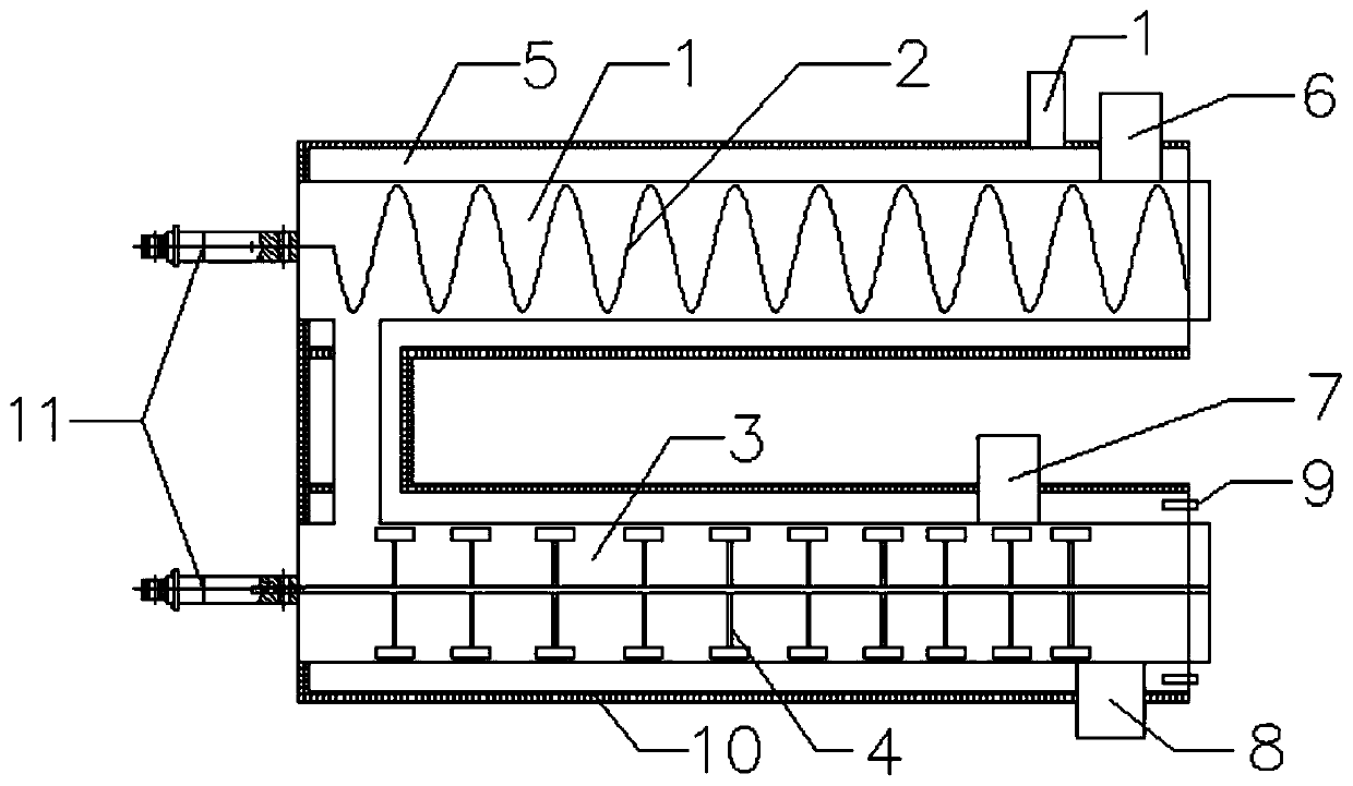
[0040] An organic waste pyrolysis device mainly includes a low-temperature pyrolysis chamber 1 , a high-temperature pyrolysis chamber 3 , a flue gas chamber 5 , an insulating layer 10 and a motor 11 .

[0041] There is a material inlet 6 on the top of one end of the low-temperature pyrolysis chamber 1, and the waste material enters the low-temperature pyrolysis chamber 1, where moisture removal, partial melting, and primary pyrolysis reactions mainly occur; The chamber 1 rotates to stir and convey the garbage materials. The distance between the spiral blade and the inner wall of the low-temperature pyrolysis chamber 1 is 2-5mm, and in this embodiment it is 2mm.

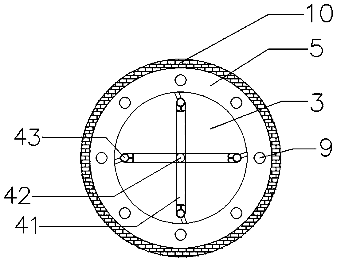
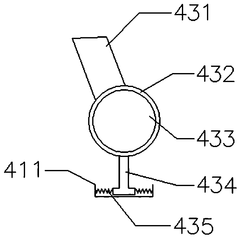
[0042] The far end of the high-temperature pyrolysis chamber 3 has a pyrolysis steam outlet 7 and a pyrolysis solid outlet 8, and there is a stirring coke scraper 4 inside. And the secondary cracking and polycondensation reaction of the primary pyrolysis product occurs; the stirring coke scraper 4 is composed of a sti...

Embodiment 2

[0052] Pyrolysis treatment process of an organic waste:

[0053] The specific components of domestic waste in a waste station are as follows:

[0054]

[0055] The process is as follows:

[0056] 1. After sorting and removing inorganic substances such as slag, broken glass, metal, etc., the garbage is crushed and sent to the low-temperature pyrolysis chamber of the pyrolysis device;

[0057] 2. In the low-temperature pyrolysis chamber, under the shaftless spiral stirring, the garbage is dehydrated, partially melted, and the primary pyrolysis reaction occurs;

[0058] 3. The pyrolysis products produced in the low-temperature pyrolysis chamber enter the high-temperature pyrolysis chamber, and under the agitation of the stirring coke scraper, further deep pyrolysis occurs, and secondary cracking and polycondensation reactions occur;

[0059] 4 The high-temperature pyrolysis steam generated by pyrolysis is exported from the pyrolysis steam outlet, and the pyrolysis solid is d...


PUM


Abstract

The embodiment of the invention provides an organic garbage pyrolysis device. The device mainly comprises a low-temperature pyrolysis chamber, a high-temperature pyrolysis chamber, a smoke chamber, aheat preservation layer and a motor, wherein the low-temperature pyrolysis chamber adopts shaftless spiral stirring and garbage material conveying; a stirring scraper in the high-temperature pyrolysischamber mixes materials, and scrapes off coked materials on a heating surface; high-temperature oil gas generated by organic garbage pyrolysis is directly combusted, and hot smoke flows in the smokechamber in the direction opposite to the garbage material conveying direction and exchanges heat with the materials in the high-temperature pyrolysis chamber and the low-temperature pyrolysis chamberin sequence; a screw and a coke scraper are arranged in the pyrolysis chamber, so that materials are uniformly heated, and coking is reduced; segmented pyrolysis realizes high-temperature direct combustion of high-efficiency pyrolysis garbage pyrolysis oil gas of different kinds of garbage, high-temperature sensible heat is effectively utilized, the temperature of combustion smoke is increased, and pollution is reduced; and the smoke is indirectly heated, pyrolysis gas is not mixed with the smoke, the heat value is high, and subsequent utilization is easy. The embodiment of the invention further provides a garbage pyrolysis treatment method using the organic garbage pyrolysis device.

Description

technical field [0001] The invention belongs to the technical field of garbage pyrolysis treatment, in particular to an organic garbage pyrolysis device. The present invention also provides a method for pyrolyzing organic waste by using the organic waste pyrolysis device. Background technique [0002] With the rapid development of the national economy, the amount of domestic waste and industrial organic solid waste is increasing year by year. Among them, the total amount of domestic waste alone is expected to reach 409 million tons in 2030. Garbage pollution has become an important urban life problem and Social problems. Due to the huge output of urban domestic waste, if it is not handled properly, it will face a situation of "garbage siege". When domestic waste enters the environment, it will not only pollute water, air, and soil, but also seriously threaten human survival and health. Organic matter, sludge, oil sludge, waste plastics, medical waste, etc. in domestic waste...

Claims


Application Information

Patent Timeline
IPC IPC(8): C10B53/00C10B57/02
CPCC10B53/00C10B57/02
Inventor 陆强阳实秀
Owner 湖南华仁宏顺科技有限公司
Learn More