Well mouth casing gas pressurizing recovery device, system and method and application

A technology of recovery device and booster device, which is applied in earthwork drilling, wellbore/well components, liquid variable capacity machinery, etc., and can solve problems such as inability to recover casing gas, difficulty in low temperature operation, and increased power consumption , to achieve the effect of shortening the time rate of finding abnormal oil wells, reducing the labor intensity of employees, and reducing potential safety hazards

Active Publication Date: 2020-04-21
PETROCHINA CO LTD
View PDF10 Cites 2 Cited by
  • Summary
  • Abstract
  • Description
  • Claims
  • Application Information

AI Technical Summary

Problems solved by technology

[0004] 1. There is a problem with the recovery technology of constant pressure valve and bleed valve, that is, oil wells with back pressure higher than casing pressure cannot recover casing gas
[0005] 2. The problem with the recovery technology of the interlocking low-pressure pumping cylinder is that the sealing part of the pumping cylinder has high requirements on the environment, and it is hard-connected to the beam of the pumping unit, changing the mechanical structure of the four-linkage operation of the pumping unit, and there are many faults
[0006] 3. The problem with the pressurized recovery technology of the compressor unit is that the equipment and maintenance costs are high, the power consumption is increased, and the applicability of the well site with a small amount of associated gas is not strong
[0007] 4. The problem of using synchronous rotary compressor recovery technology is frequent equipment maintenance during operation, difficulty in low-temperature operation, and weak gas-carrying capacity
[0008] 5. The problem of adopting gas-gathering pipeline network recovery technology in individual well groups is that the cost of pipeline laying is high, and pipelines are easy to freeze and block in winter operation

Method used


Image

  • Well mouth casing gas pressurizing recovery device, system and method and application
  • Well mouth casing gas pressurizing recovery device, system and method and application

Examples


Embodiment 1

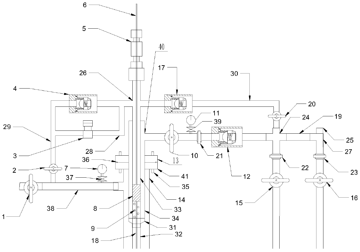
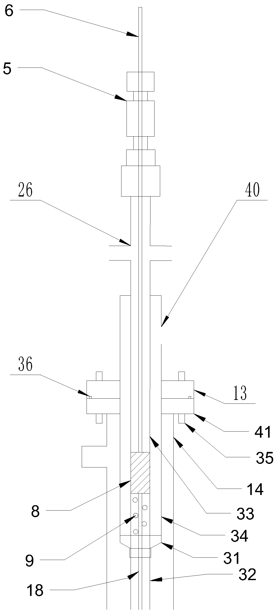
[0041] according to figure 1 The shown oil well casing gas pressurized recovery device includes a polished rod sealer 5, a polished rod 6, a wellhead cross 26, a built-in plunger 8 of the pressurized device, a screen tube 9, a variable diameter collar 31, a work cylinder 33, The sleeve 34 and the sucker rod 18; the polished rod sealer 5 is connected to the work cylinder 33 through the wellhead spool 26; the polished rod 6 extends into the work cylinder 33 through the polished rod sealer 5, and is placed in the work cylinder 33 The pressurization device inside is connected with a built-in plunger 8, and the screen tube 9 is connected to the lower part of the working cylinder 33; the sleeve 34 is connected to the outside of the working cylinder 33 and the screen tube 9, and the lower port of the sleeve 34 passes through a reducing collar 31 It is connected with the lower port of the screen tube 9, the outer wall of the sleeve 34 is provided with a connecting piece, and the upper...

Embodiment 2

[0046] according to figure 1 The shown oil well casing gas pressurized recovery device is different from the first embodiment in that the connector provided on the outer wall of the sleeve 34 is the first flange 13, and the lower surface of the first flange 13 is opened. There are grooves.

[0047] In actual use, the connecting piece on the outer side wall of the sleeve 34 adopts the technical scheme of the first flange 13, which can easily connect the oil well casing gas pressurized recovery device and the oil pipe 32 through the flange screw 35, which is low in cost and has Better connection effect. The groove on the lower surface of the first flange 13 is used for placing the sealing steel ring 36 to ensure a good sealing effect.

Embodiment 3

[0049] according to figure 1 The shown oil well casing gas pressurized recovery system includes at least one oil well casing gas pressurized recovery device, and also includes casing gate 1, casing 14, tubing 32, casing gas pipeline 38, casing gas collection Pipeline 29, exhaust pipeline 30 and wellhead oil collection pipeline 19; the oil pipe 32 is connected to the variable diameter collar 31 of the oil well casing gas pressurization recovery device; the casing 14 is sleeved in the oil well casing gas pressurization Outside the recovery device, the upper port of the sleeve pipe 14 is connected to the connector provided on the outer side wall of the sleeve 34; connection; the input end of the casing gas collection line 29 is connected to the casing gas line 38, and the output end of the casing gas collection line 29 is connected to the wellhead cross 26; the input end of the exhaust pipeline 30 is connected to the wellhead cross 26 , the output end of the exhaust pipeline 30 ...


PUM


Abstract

The invention belongs to the technical field of well mouth casing gas recovery, and particularly relates to a well mouth casing gas pressurizing recovery device, system and method and application. Through the well mouth casing gas pressurizing recovery device composed of a polished rod sealer, a polished rod, a well mouth four-way part, a pressurization device built-in plunger, a sieve pipe, a sub-coupling, a working barrel and a sucker rod, when the polished rod reciprocates and works synchronously with a downhole oil well pump, the suck-in and compressing technological process of the casinggas is completed in the working barrel, after pressurizing, the gas enters an oil collecting pipeline in the well mouth casing gas pressurizing recovery system to be subjected to pressurizing recovery, and the complete casing gas pressurizing recovery process is realized. The operation energy of a pumping unit is completely used in the whole pressurization process, and the working of the pumping unit and the normal production of an oil well are not influenced. The well mouth casing gas pressurizing recovery device can effectively improve the casing gas pressurizing recovery efficiency and hasthe advantages of being low in construction cost, convenient to install, automatic in operation and free of manual operation.

Description

technical field [0001] The invention belongs to the technical field of wellhead casing gas recovery, and in particular relates to a wellhead casing gas pressurized recovery device, system, method and application. Background technique [0002] In recent years, various oil fields have strictly implemented the national environmental protection and energy conservation and emission reduction policies, and carried out a lot of work in the comprehensive utilization of associated gas, and achieved good results. The associated gas production capacity of an oilfield is 9.7×10⁸m 3 / a, the utilization rate is about 80%, the ineffective venting of associated gas is about 20%, and the venting volume is about 59×104m 3 / d, resulting in the waste of some natural resources and the pollution of the ecological environment, and there is still a huge potential for the comprehensive utilization of associated gas. [0003] There are mainly five traditional technologies for recovery of wellhead c...

Claims


Application Information

Patent Timeline
Patent Type & Authority Applications(China)
IPC IPC(8): E21B43/00F04B37/12F04B35/06
CPCE21B43/00F04B37/12F04B35/06
Inventor 侯宁郑刚黎成程颢安会云罗庆梅晏耿成冯建设陈堂锁王凯孙浩王曼石磊吕旭潘昊
Owner PETROCHINA CO LTD
Why Eureka
Try Eureka