Boosted circuit of direct-hanging high-voltage power supply and soft start method

A high-voltage power supply and boost circuit technology, applied in the power supply field, can solve problems such as diode overvoltage damage, achieve the effects of reducing volume, reducing inductor volume, and reducing costs

Pending Publication Date: 2020-04-21
浙江日风电气股份有限公司
View PDF0 Cites 2 Cited by
  • Summary
  • Abstract
  • Description
  • Claims
  • Application Information

AI Technical Summary

Problems solved by technology

[0006] image 3 In the circuit, when the switch KS2 is closed, the high-voltage battery charges C2 and C3 until the BUS voltage reaches the soft-start voltage amplitude, then KS2 is opened and K2 is closed. At this time, the BUS voltage is equal to the high-voltage battery voltage, and at this time due

Method used


Image

  • Boosted circuit of direct-hanging high-voltage power supply and soft start method
  • Boosted circuit of direct-hanging high-voltage power supply and soft start method
  • Boosted circuit of direct-hanging high-voltage power supply and soft start method

Examples


Embodiment 1

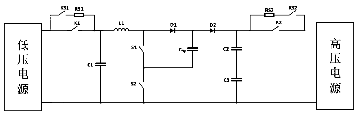
[0027] see Figure 4 , Embodiment 1: In the embodiment of the present invention, a booster circuit directly connected to a high-voltage power supply,

[0028] A booster circuit directly connected to a high-voltage power supply, comprising an inductor L1, a switch S1, a diode D1, and a diode D2, one end of the inductor L1 is connected to a capacitor C1, a switch K1, and the anode of a diode D3, and the other end of the switch K1 is connected to a low-voltage power supply , the other end of the inductor L1 is connected to the switch S1 and the anode of the diode D1, the cathode of the diode D1 is connected to the capacitor Cfly, the resistor RS3 and the anode of the diode D2, the other end of the switch S1 is connected to the switch S2 and the other end of the capacitor Cfly, and the other end of the capacitor C1 One end is connected to the other end of the switch S2, the other end of the low-voltage power supply, the capacitor C3 and the high-voltage power supply, the cathode o...

Embodiment 2

[0030] Embodiment 2: on the basis of embodiment 1, as Figure 5 As shown, KS3 and D4 are added, among which KS3 is a normally closed switch. When the control system is powered on, the host sends a power-on command, and the power supply enters the start-up state. First, KS2 is closed, and the high-voltage power supply is charged through KS2, RS2 and C2, C3. At the same time, the high-voltage power supply forms a charging circuit through KS2, RS2, KS3, Cfly and C3, until the system detects that the voltages of C2, C3 and Cfly meet the starting voltage, close K2, and disconnect KS2 and KS3 at the same time, at this time due to C2 The voltage is the same as that of Cfly, so there is no loss in the disconnection of KS3, and the DCDC power supply and the high voltage power supply side are hung together. Then close KS1, and the low-voltage power supply side charges C1 through KS1 and RS1. Similarly, when it is detected that the voltage of C1 meets the starting conditions, close K1 an...


PUM


Abstract

The invention discloses a boosted circuit of a direct-hanging high-voltage power supply and a soft start method. The boosted circuit comprises an inductor L1, a switch S1, a diode D1 and a diode D2. One end of the inductor L1 is connected with a capacitor C1, the switch K1 and the anode of the diode D3; the other end of the switch K1 is connected with a low-voltage power supply; the other end of the inductor L1 is connected with the switch S1 and the anode of the diode D1; the cathode of the diode D1 is connected with a capacitor Cfly, a resistor RS3 and the anode of the diode D2. In an outputdirect-hanging high-voltage power supply application scene circuit, a novel three-level flying capacitor circuit is used and the unique soft start circuit is cooperated and all the switching voltagelevel of the system can be reduced by half. The low-voltage semiconductor switching characteristic is good and the selectivity is high so that the high frequency of the whole circuit can be realized,the inductance volume can be reduced, the volume of the whole mechanism can be reduced, and the cost of the whole system can be reduced.

Description

technical field [0001] The invention relates to the technical field of power supplies, in particular to a step-up circuit and a soft-start method for a direct-connected high-voltage power supply. Background technique [0002] In view of the increasingly serious environmental pollution, the country has begun to vigorously develop new energy vehicles, especially hydrogen fuel cell vehicles. Because the front end of the fuel cell receives hydrogen and oxygen, after the electrochemical reaction, in addition to generating electricity, the discharge is water. Without any pollution, it is regarded as an ideal clean energy. [0003] Although the fuel cell has many advantages, as a vehicle energy source, its output voltage and current characteristics are soft, its rated operating voltage is low, and it is unstable under interference. figure 1 It is shown that a DC / DC converter needs to be added between the fuel cell and the motor controller to convert and stabilize the voltage, so t...

Claims


Application Information

Patent Timeline
IPC IPC(8): H02M3/20
CPCH02M3/20
Inventor 陈建明王波卢钢章旌红
Owner 浙江日风电气股份有限公司
Why Eureka
Try Eureka