Liquid phase hydrogenation system and liquid phase hydrogenation method

A technology of liquid-phase hydrogenation and hydrogenation reaction, applied in the fields of hydrogenation treatment process, chemical instruments and methods, petroleum industry, etc., can solve the problems of high cost, difficult operation, hydrogen waste, etc., and reduce hydrogen consumption and energy consumption , prolong the service life and improve the utilization rate

Active Publication Date: 2020-04-28
CHINA PETROLEUM & CHEM CORP +1
View PDF13 Cites 6 Cited by
  • Summary
  • Abstract
  • Description
  • Claims
  • Application Information

AI Technical Summary

Problems solved by technology

In this method, on the one hand, the combined use of the reaction system, circulation system and heating furnace system makes the reaction process very complicated, costly and difficult to operate; on the other hand, a large amount of circulating materials are introduced, which increases the total vol...

Method used


Image

  • Liquid phase hydrogenation system and liquid phase hydrogenation method
  • Liquid phase hydrogenation system and liquid phase hydrogenation method
  • Liquid phase hydrogenation system and liquid phase hydrogenation method

Examples


Embodiment 1

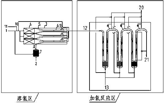
[0065] The hydrogen dissolving equipment in the hydrogen dissolving zone and the tubular reactor in the high-efficiency hydrogenation reaction zone are adopted in the present invention, wherein the hydrogen dissolving equipment is the same as in comparative example 3, and the tubular reactor in the high-efficiency hydrogenation zone is the same as in comparative example 2.

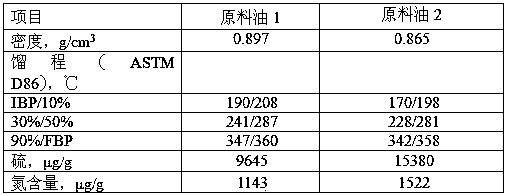
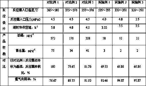
[0066] The feed oil 1 (straight-run diesel) and feed oil 2 (catalyzed diesel) in Table 1 were respectively used as raw materials, and the reaction products were obtained after hydrogenation reaction. The reaction conditions and product properties are shown in Table 2.

Embodiment 2

[0068] Using the hydrogen dissolving equipment in the hydrogen dissolving zone of the present invention and the tubular reactor in the high-efficiency hydrogenation zone, first, the raw material oil and hydrogen are formed into a stable "gas-in-oil" mixed fluid by using the hydrogen dissolving equipment in the present invention, and the The fluid is introduced into the tubular reactor in the high-efficiency hydrogenation zone for liquid-phase hydrogenation reaction.

[0069] The preliminary hydrogen dissolving section in the hydrogen dissolving equipment in the hydrogen dissolving area adopts a cylindrical internal filling spiral plate spoiler assembly, the residence time is 5.0 minutes, and the low-pressure escaped hydrogen is recycled, and the flow rate is 0.015% of the raw material mass; the accelerated dissolving The contraction angle of the hydrogen section is 20°, and the length ratio of the accelerated hydrogen dissolution section to the hydrogen release section is 1:15;...

Embodiment 3

[0073] Using the hydrogen dissolving equipment in the hydrogen dissolving zone of the present invention and the tubular reactor in the high-efficiency hydrogenation zone, first, the raw material oil and hydrogen are formed into a stable "gas-in-oil" mixed fluid by using the hydrogen dissolving equipment in the present invention, and the The fluid is introduced into a conventional fixed-bed liquid-phase hydrogenation reactor for liquid-phase hydrogenation reaction.

[0074] The preliminary hydrogen dissolving section of the hydrogen dissolving equipment in the hydrogen dissolving area adopts a cylindrical interior filled with rotating vane spoiler components, and the residence time is 4.5 minutes. The contraction angle of the section is 20°, and the length ratio of the accelerated hydrogen dissolution section to the hydrogen release section is 1:8; the operating conditions of the introduction position of the hydrogen-rich gas-liquid mixture in the accelerated hydrogen dissolutio...


PUM


Abstract

The invention discloses a liquid phase hydrogenation system and a liquid phase hydrogenation method. The system comprises a hydrogen dissolving zone and an efficient hydrogenation reaction zone, wherein the hydrogen dissolving zone is internally provided with a plurality of hydrogen dissolving devices, each hydrogen dissolving device comprises a hydrogen dissolving device shell, the hydrogen dissolving device shell internally comprises a plurality of hydrogen dissolving assemblies connected in parallel, the efficient hydrogenation reaction zone comprises a plurality of tubular reactors connected in series, and the tubular reactor is in a U shape and comprises straight pipe sections on the two sides and a horizontal section with the bottom communicated with the straight pipe sections on thetwo sides. According to the method disclosed by the invention, a gas-in-oil type gas-liquid mixed fluid formed in the hydrogen dissolving zone used as the feed of a liquid-phase hydrogenation reaction enters the U-shaped tubular reactor in the efficient hydrogenation reaction zone and is subjected to a deep hydrogenation reaction, so that the supplementary hydrogen-oil ratio during the hydrogenation reaction process can be substantially reduced, the hydrogen utilization rate can be improved, the hydrogen consumption and the energy consumption can be reduced, H2S, NH3 and other gases producedduring the reaction process can be continuously removed from the reaction system, the high hydrogenation reaction rate and the high reaction efficiency can be improved and maintained, and the deep hydrogenation reaction can be achieved.

Description

technical field [0001] The invention belongs to the field of petrochemical industry, and specifically relates to a liquid-phase hydrogenation system and a liquid-phase hydrogenation method. Background technique [0002] Compared with the conventional trickle bed gas\liquid\solid three-phase hydrogenation process, the liquid phase hydrogenation technology has the advantages of simple process flow, saving investment, reducing production cost, and high reaction efficiency. In the conventional trickle bed hydrogenation reaction process, hydrogen is mainly used for mass transfer, that is, the speed at which hydrogen diffuses from the gas phase and dissolves into oil is the rate-controlling step of the entire hydrogenation reaction. The liquid-phase hydrogenation process eliminates the influence of hydrogen diffusion and mass transfer, so that the hydrogenation reaction is carried out in the kinetic control zone, that is, the hydrogen is dissolved in the raw material oil to meet t...

Claims


Application Information

Patent Timeline
IPC IPC(8): B01J8/06C10G65/06
CPCB01J8/06C10G65/06
Inventor 杨秀娜于淼阮宗琳王昊辰金平
Owner CHINA PETROLEUM & CHEM CORP
Why Eureka
Try Eureka