Ammonia supply system and method for preparing sodium carbonate
A soda ash and ammonia supply technology, applied in the direction of carbonate preparations, sustainable manufacturing/processing, climate sustainability, etc., can solve problems such as personnel poisoning and suffocation, fire and explosion, liquid ammonia leakage, etc., to avoid accidents and improve Temperature, the effect of reducing energy consumption
- Summary
- Abstract
- Description
- Claims
- Application Information
AI Technical Summary
Problems solved by technology
Method used
Image

Examples
Embodiment 1
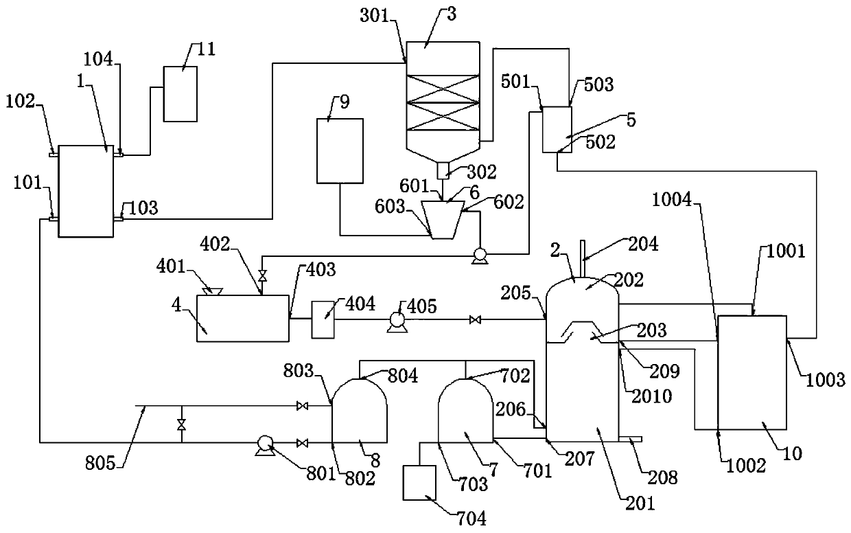
[0032] A kind of ammonia supply system for preparing soda ash as an embodiment of the present invention, such as figure 1 As shown, including heat exchange unit, distillation unit, ammonium chloride preparation unit and calcium hydroxide preparation unit;
[0033] The ammonium chloride preparation unit comprises an ammonium chloride dissolving tank 4, a cyclone separator 6 and a tail gas scrubber 3, and the ammonium chloride dissolving tank 4 is provided with a liquid inlet 402, a liquid outlet 403 and a solid feed port 401, and the tail gas scrubber The upper part of 3 is provided with a washing water inlet 301, the lower part of the tail gas scrubber 3 is provided with a washing liquid outlet 302 and ash tail gas inlet, and the cyclone separator 6 is provided with a feed inlet 601 of the cyclone separator and a liquid outlet 602 of the cyclone separator , the washing liquid outlet 302 of the tail gas scrubber is communicated with the feed inlet 601 pipeline of the cyclone se...
PUM
 Abstract
Description
Claims
Application Information