
Cutter compensation and correction method and system of machine tool

A technology of machine tools and cutting tools, which is applied in the field of mobile phone case processing equipment, can solve problems that affect product size accuracy, take a long time to adjust the machine, and deflection of the cutter head, so as to improve product yield, reduce machine adjustment time, and increase processing output. Effect

Active Publication Date: 2020-05-08
福建省嘉泰智能装备有限公司
View PDF10 Cites 2 Cited by
  • Summary
  • Abstract
  • Description
  • Claims
  • Application Information

AI Technical Summary

Problems solved by technology

[0002] Glass mobile phone shell products are processed on processing equipment, and the end of the tool for processing glass is equipped with a grinding wheel. Due to many factors, it will affect the dimensional accuracy of the product
The main reasons for the uncontrollable or large fluctuation range of the processing size deviation: 1. The diameter difference of the grinding wheel itself; 2. The normal wear of the grinding wheel; 3. The deflection of the grinding wheel, resulting in inconsistent wear; 4. The deflection of the cutter head; 5. The deviation of the machine tool accuracy ;6. Abnormal wear and tear of the grinding wheel, failure within the service life; 7. Rigid deformation of the grinding wheel body;
In order to stabilize the production, it is necessary for the machine operator to adjust the machine tool. However, these adjustments require high-level adjustment engineers, and the adjustment takes a long time, and the yield rate of different levels of adjustment masters is different.

Method used


Image

  • Cutter compensation and correction method and system of machine tool
  • Cutter compensation and correction method and system of machine tool
  • Cutter compensation and correction method and system of machine tool

Examples


Embodiment 1

[0037] A tool correction method for a machine tool of the present invention comprises the following steps,

[0038] Accumulate a large amount of wear data of the entire life cycle of the grinding wheel, and calculate the wear trend coefficient S of the grinding wheel according to the big data model of grinding wheel wear;

[0039] A large amount of grinding wheel wear-processing time data is analyzed to establish a big data model of grinding wheel wear.

[0040] Accumulate a large amount of grinding wheel deflection data, as well as the cutting force change data under the corresponding grinding wheel deflection and machine tool control accuracy data in the process of processing products, and calculate the impact of cutting force change and grinding wheel deflection on machine tool control based on the big data model of machine tool control accuracy. The correlation factor coefficient P of the influence of precision;

[0041] The establishment method of the big data model of m...

Embodiment 2

[0053] A tool correction method for a machine tool of the present invention comprises the following steps,

[0054]The first piece tool compensation step, the first piece tool compensation step is at the front, the first piece tool compensation step includes: when the machine tool is replaced with a new grinding wheel, calculate the first piece tool compensation value required by the specified D position of the machine tool according to the deflection data of the new grinding wheel, The machine tool corrects the position of the tool according to the tool compensation value of the first piece.

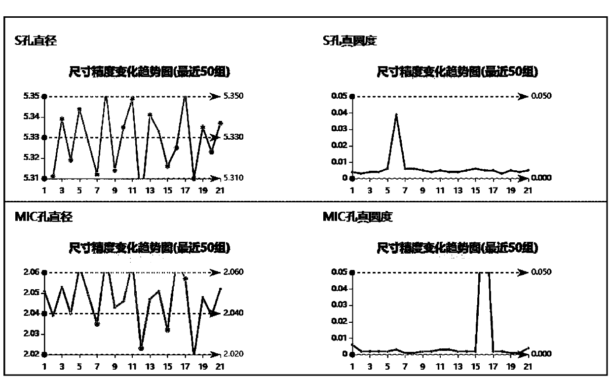
[0055] Accumulate a large amount of wear data of the entire life cycle of the grinding wheel, and calculate the wear trend coefficient S of the grinding wheel according to the big data model of the wear of the grinding wheel; a large number of wear data of the entire life cycle of the grinding wheel are the latest 50 groups.

[0056] Accumulate a large amount of grinding wheel deflectio...

Embodiment 3

[0066] A tool correction system for a machine tool, comprising:

[0067] The grinding wheel data acquisition terminal is used to measure the grinding wheel, collect the effective processing diameter data, deflection data, rigid deformation data, and wear data of the grinding wheel, and send the collected grinding wheel data to the database terminal;

[0068] The machine tool data acquisition terminal is used to collect the cutting force change data, control precision data, motor torque data, spindle deflection data, and spindle box deflection data of the machine tool, and send the collected machine tool data to the database terminal;

[0069] The product size data collection terminal is used to measure the product size, collect product size data, and send the collected product size data to the database side;

[0070] The database end is used to store grinding wheel data, machine tool data, and product size data;

[0071] The data processing background is connected to the data...


PUM


Abstract

A cutter compensation and correction method of a machine tool comprises the following steps that an abrasion wheel wear trend coefficient S is calculated; a correlation factor coefficient P of the influence of cutting force changes and abrasion wheel deflection on the machine tool control accuracy is calculated; a correlation factor M1 of the influence of the mechanical factor of the machine toolon the machining size is calculated; a first part actual compensation value M2 is calculated according to the effective machining diameter, deflection data and rigid deformation data of an existing abrasion wheel installed on the machine tool; the size of a product to be machined is measured, and the size deviation of the product is calculated; a cutter compensation value X is calculated through acompensation and correction algorithm according to the abrasion wheel wear trend coefficient S, the correlation factor coefficient P, the correlation factor M1, the first part actual compensation value M2 and the size deviation of the product; and when the product is machined by the machine tool, the cutter position is compensated and corrected according to the cutter compensation value X. By theadoption of the cutter compensation and correction method of the machine tool, the cutter position can be automatically compensated and corrected, the time adjustment time is shortened, the product yield can be improved, and the machining output of a machining facility is improved.

Description

technical field [0001] The invention relates to the field of mobile phone shell processing equipment, in particular to a tool correction method and system for a machine tool. Background technique [0002] Glass mobile phone case products are processed on processing equipment, and the end of the tool for processing glass is equipped with a grinding wheel. Due to the influence of many factors, the dimensional accuracy of the product will be affected. The main reasons for the uncontrollable or large fluctuation range of the processing size deviation: 1. The diameter difference of the grinding wheel itself; 2. The normal wear of the grinding wheel; 3. The deflection of the grinding wheel, resulting in inconsistent wear; 4. The deflection of the cutter head; 5. The deviation of the machine tool accuracy ; 6. The grinding wheel is abnormally worn out and fails within the service life; 7. The body of the grinding wheel is rigidly deformed; 8. The cutter head clips chips. In order ...

Claims


Application Information

Patent Timeline
Patent Type & Authority Applications(China)
IPC IPC(8): B24B51/00G05B19/404
CPCB24B51/00G05B19/404G05B2219/35408
Inventor 李敏之
Owner 福建省嘉泰智能装备有限公司
Learn More