CO conversion process for co-producing synthesis gas and hydrogen and isothermal shift converter

An isothermal shift and synthesis gas technology, applied in the field of CO shift technology, can solve the problems of large system pressure drop, many equipment, and large investment, and achieve the effects of small system pressure drop, flexible operation, and low investment

Pending Publication Date: 2020-05-08
SINOPEC NINGBO ENG +2
View PDF8 Cites 0 Cited by
  • Summary
  • Abstract
  • Description
  • Claims
  • Application Information

AI Technical Summary

Problems solved by technology

[0004] At present, the process design of CO shift to synthesis gas or hydrogen supporting coal-water slurry gasification mostly adopts the method of "multi-stage adiabatic reaction + indirect heat energy recovery" to set up the process. A series of problems such as high energy consumption, large system pressure drop, and short catalyst life
[0005] Among the isothermal shift hydrogen production processes developed in recent years, whether it is an adiabatic shift series isothermal shift process, an isothermal shift series adiabatic shift process, or a double isothermal shift furnace series process, it is a single production of synthesis gas or hydrogen, which cannot be combined. Production of syngas and hydrogen

Method used


Image

  • CO conversion process for co-producing synthesis gas and hydrogen and isothermal shift converter
  • CO conversion process for co-producing synthesis gas and hydrogen and isothermal shift converter
  • CO conversion process for co-producing synthesis gas and hydrogen and isothermal shift converter

Examples


Embodiment Construction

[0050] The present invention will be further described in detail below in conjunction with the accompanying drawings and embodiments.

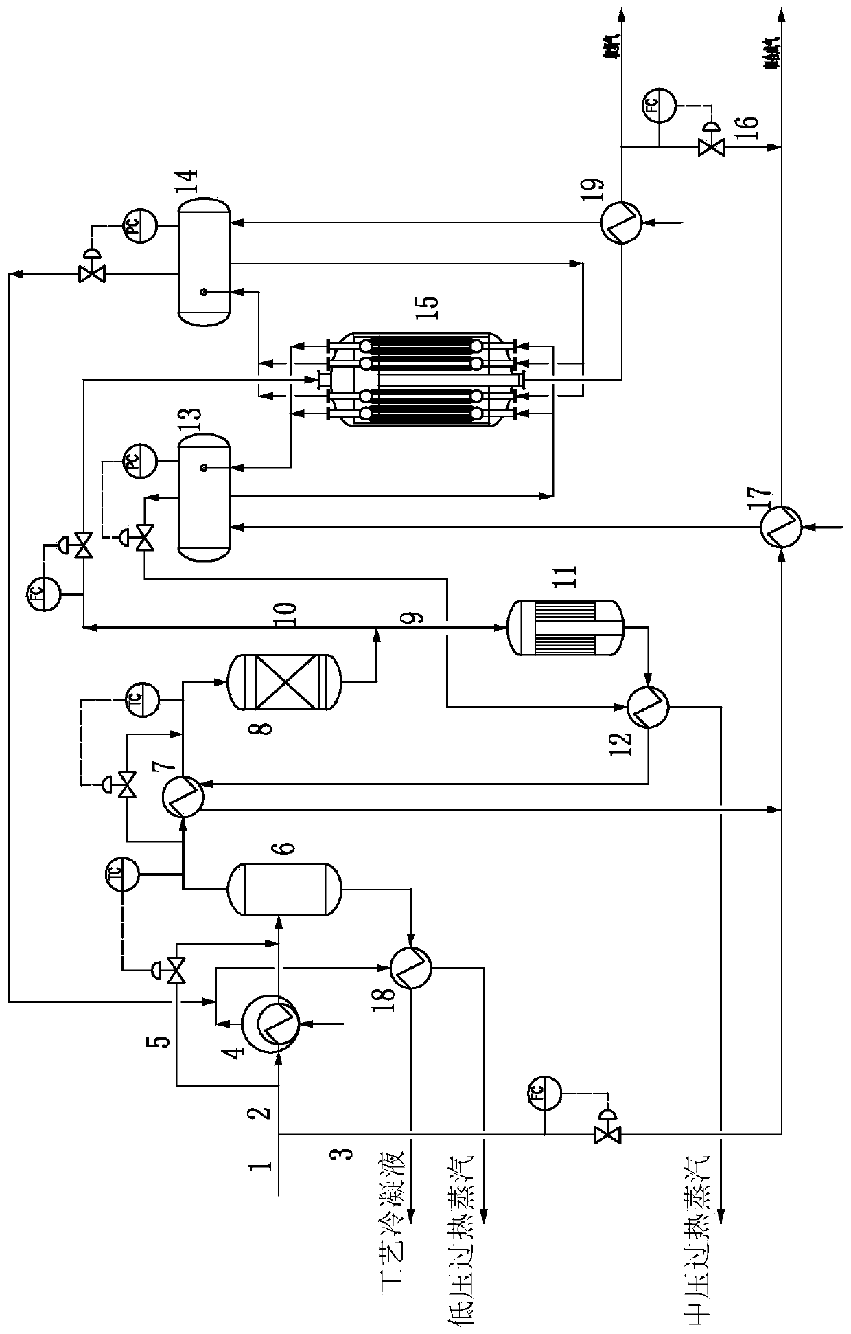
[0051] Such as figure 1 As shown, the crude gas 1 from the coal-water slurry gasification unit with a molar water-gas ratio of 1.67, a temperature of 246°C, and a pressure of 6.3MPaG is divided into two streams, one of which is about 22v% crude gas as the non-shifted gas 3; A raw gas of about 78v% is used as the shift gas 2 .

[0052] The shifted gas 2 enters the low-pressure steam generator 4 to recover heat, is cooled to 235°C, and then enters the feed separator 6 for gas-liquid separation, and the condensate is separated, and at the same time, low-pressure saturated steam of 0.45MPaG is produced by-product, and the low-pressure steam generator 4 There is a first temperature adjustment auxiliary line 5 connected in parallel. By adjusting the valve opening of the auxiliary line 5, the temperature of the crude gas entering the feed separator ...


PUM


Abstract

The invention relates to a CO conversion process for co-producing synthesis gas and hydrogen and an isothermal shift converter. The CO conversion process comprises the following steps: dividing raw gas from a coal water slurry gasification device into two streams, taking one stream as non-conversion gas, subjecting the other stream to heat recovery, condensate separation and heat exchange, and then dividing the other stream into two streams; allowing the first stream to enter an adiabatic shift converter for a shift reaction, mixing synthesis gas discharged from the adiabatic shift converter with the non-conversion gas after heat recovery and then conveying the formed mixture to down stream; allowing the second stream to enter the isothermal shift converter for a medium-temperature shift reaction and a low-temperature shift reaction, wherein medium-pressure saturated steam and low-pressure saturated steam are by-produced; exchanging heat between the medium-pressure saturated steam andthe synthesis gas discharged from the adiabatic shift converter to obtain medium-pressure superheated steam; carrying out heat exchange on the low-pressure saturated steam and condensate to obtain low-pressure superheated steam; and conveying crude hydrogen obtained at the outlet of the isothermal shift converter to down stream after heat recovery.

Description

technical field [0001] The invention relates to a CO shift process, in particular to a CO shift process and an isothermal shift furnace for co-producing synthesis gas and hydrogen. Background technique [0002] my country is a country short of oil, gas, and rich in coal. The specific resources determine that the source of energy and chemical raw materials in my country must be mainly coal. Coal gasification is an important method for chemical processing of coal and the key to realize clean utilization of coal. Coal gasification technology is the core technology and leading technology of coal-based chemical industry. Among them, gasification technology using coal water slurry as raw material is an important branch, mainly multi-nozzle opposed coal water slurry gasification technology, GE gasification technology, etc. The characteristics of this type of gasification technology are that the carbon monoxide dry basis content in the crude gas produced is 38v%-50v%, and the wate...

Claims


Application Information

Patent Timeline
IPC IPC(8): C01B3/16C01B3/14B01J8/02B01J8/04F22B1/18
CPCC01B3/16C01B3/14B01J8/02B01J8/04B01J8/0292B01J8/0285F22B1/18B01J2208/00044B01J2208/00132C01B2203/0288C01B2203/0883C01B2203/1052C01B2203/1041Y02P20/10
Inventor 许仁春吴艳波亢万忠徐洁相红霞傅晓欢田贵春李垚洪吴宗城应钊
Owner SINOPEC NINGBO ENG
Why Eureka
Try Eureka