
Copper smelting slag slow cooling system and slow cooling method

A copper smelting slag and slow cooling technology, which is applied in the direction of furnaces, furnace components, and discharged materials, can solve the problems of high grinding production cost, long cooling time, and large site area, and achieve easy crushing and grinding, Less pressure loss in the pipeline and the effect of reducing the floor space

Pending Publication Date: 2020-05-08
广西南国铜业有限责任公司
View PDF4 Cites 2 Cited by
  • Summary
  • Abstract
  • Description
  • Claims
  • Application Information

AI Technical Summary

Problems solved by technology

[0004] The above-mentioned slow cooling method has the following problems: (1) a slag chartered vehicle channel needs to be set up in the slow cooling field, and the required site area is large; (2) the laying of the water supply pipeline is complicated, and in addition, the inside of the pipeline is easy to scale, and the amount of water in the middle and rear sections of the pipeline is often Insufficient cooling effect leads to poor cooling effect, high slag hardness, long overall cooling time, low turnover rate of slag ladles, which easily lead to safety accidents; (3) slag charter trucks frequently receive, release, and turn over ladles, resulting in high energy consumption and maintenance costs , which directly leads to high production costs for slag slow cooling, crushing, and grinding
Although the above two technical solutions have solved the various problems of the aforementioned fixed spray slow cooling to a certain extent, and have effectively improved the automation of the slag slow cooling, for a copper metallurgical production enterprise, a large number of slag, and the weight of a slag bag is as high as 75t, a slag bag car can only pull several slag bags at a time / a cooling box can only load one slag bag at a time for cooling, that is, according to the Chinese invention patent application CN 104630396 A and China The device of utility model patent CN 208183045 U is used for cooling, and only a few slag bags can be cooled at one time, and the cooling process requires a slag bag car to pull the slag bags back and forth for cooling / need to load the slag bags into the cooling box and transport them into the transmission channel After cooling and taking it out, due to the heavy weight of the slag bag, huge energy consumption will be generated during the cooling and transportation process, and it cannot be applied to the slow cooling of a large number of slag bags, that is, the above-mentioned device cannot be effectively industrialized
In addition, the prior art also discloses a corresponding circulating water cooling system for cooling slag, for example, a Chinese utility model patent application CN 203741355 U, a circulating water cooling system capable of rapidly cooling slag, and a Chinese utility model patent CN 207811778 U Copper smelting slag slow cooling automatic control device, although these two schemes have a good cooling water circulation effect, they are not effectively integrated with the entire slag ladle slow cooling system, that is, how to use the circulating cooling system and how to effectively apply it to Technical scheme of slow cooling of slag bag

Method used


Image

  • Copper smelting slag slow cooling system and slow cooling method
  • Copper smelting slag slow cooling system and slow cooling method
  • Copper smelting slag slow cooling system and slow cooling method

Examples


Embodiment Construction

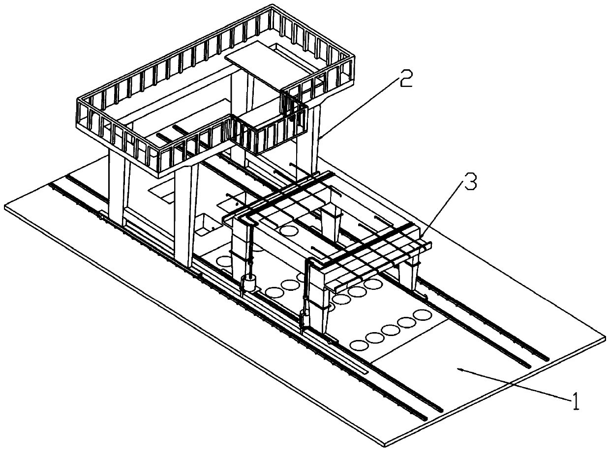
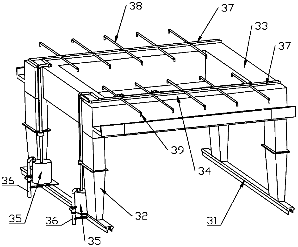
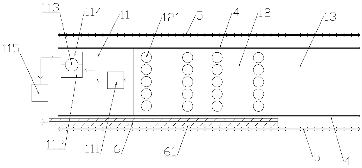
[0032] see figure 1 with image 3 , in a preferred embodiment of the present invention, a slow cooling system for copper smelting slag, comprising a slow cooling field 1 for slag, a gantry crane 2 and a sprinkler machine 3, the gantry crane 2 is used for changing and turning over the slag ladle operation, the sprinkler machine 3 is used to move and spray and cool the slag bag, and the number of the gantry crane 2 and the number of the sprinkler machine 3 are flexibly adjusted according to the actual slowly cooling slag package, that is, when the slow cooling When the amount of cold slag bag is large, multiple gantry cranes 2 and multiple sprinkler machines 3 can be operated simultaneously to improve the slow cooling efficiency of slag bag. The outside of the two long sides of the slag slow cooling field 1 is provided with a gantry crane track 5 and a sprinkler door machine track 4. The gantry crane track 5 is located outside the sprinkler door machine track 4. Machine tracks...


PUM


Abstract

The invention belongs to the technical field of metallurgical slag treatment, and particularly discloses a copper smelting slag slow cooling system and a slow cooling method thereof. The slow coolingsystem comprises a slag slow cooling field, a gantry crane and a water sprinkling door machine, wherein the gantry crane and the water sprinkling door machine can move in the length direction of the slag slow cooling field, the slag slow cooling field is divided into a water circulation area, a slag slow cooling area and a slag crushing area, the water circulation area is provided with a circulating water cooling system, and the side edge of the slag slow cooling field is provided with a process water channel; and the water sprinkling door machine is provided with a watering cross beam and a spraying pump, and the circulating water cooling system supplies water to a spraying nozzle through the process water channel, the spraying pump, a spraying main pipe and a spraying branch pipe. According to the slow cooling system, through combination of the gantry crane, a water sprinkling door machine and the circulating water cooling system, the occupied area of slag slow cooling is reduced, the slag slow cooling efficiency is high, the effect is good, and the energy consumption is low. Meanwhile, the invention further provides a slow cooling method, and the slow cooling method improves thecooling effect by adopting the slow cooling system for high-strength intermittent spraying, and the hardness of the cooled slag is low.

Description

【Technical field】 [0001] The invention relates to the technical field of metallurgical slag treatment, in particular to a slow cooling system for copper smelting slag and a slow cooling method thereof. 【Background technique】 [0002] A large amount of slag will be produced in copper pyrometallurgy. Generally, the copper content of copper slag is 2%-5%. If these slags cannot be used reasonably, it will not only cause environmental pollution, but also cause a waste of copper resources. The reuse of these slags is of great significance to resource conservation and environmental protection. [0003] At present, it has become a trend to recover copper in copper smelting slag by adopting the process of "slow cooling + crushing + grinding and floating + dehydration". Among them, "slow cooling" can make copper-containing crystal minerals gather and grow in the slag ladle, creating good conditions for flotation. Now the slow cooling method of copper smelting slag widely used in actu...

Claims


Application Information

Patent Timeline
IPC IPC(8): F27D15/02C22B7/04C22B15/00B02C23/00
CPCB02C23/00B02C2201/06C22B7/04C22B15/00F27D15/02Y02P10/20
Inventor 石立恒周南方马宝军杨德鑫邓常林万为军卢仕威
Owner 广西南国铜业有限责任公司
Learn More