Non-contact Bridge Displacement Sensing Method Based on Flexible Photoelectric Sensing Array

A photoelectric sensing and non-contact technology, applied in the direction of optical devices, instruments, measuring devices, etc., can solve the problems of centimeter level, unusable, low measurement accuracy, etc., and achieve good ductility and denaturation ability, Increased measurement stability and reduced data loss effects

Active Publication Date: 2020-10-30
ZHEJIANG UNIV
View PDF6 Cites 0 Cited by
  • Summary
  • Abstract
  • Description
  • Claims
  • Application Information

AI Technical Summary

Problems solved by technology

The dial gauge measurement method is to amplify the displacement value of the detected position by the gear rotating mechanism, and convert the detected linear reciprocating motion into the rotary rotation of the pointer to indicate its displacement value. This method is simple in equipment and can be used for multi-point measurement. Steel The chord dial indicator measurement method can only be used to measure bridge deflection on land or on frozen water in the north, and cannot be used on high bridges or in the presence of water, or a high platform must be built
The precision level measurement method is a method of measuring the height difference between two points using a level and a leveling rod. Starting from the leveling origin or any known elevation point, the elevation of each point is measured station by station along the selected leveling route, and the level is read by the leveling rod. The relative deflection can be obtained by the difference, but this method can only measure the relative value, not the absolute value
The total station measurement method is a method of triangular elevation measurement. The height difference between two points is obtained by measuring the horizontal distance and vertical angle between two points. Observation errors caused by different observation methods and experience of the observer, even if the static measurement is performed, the data is often relatively discrete, and real-time and automatic measurement cannot be achieved
The connecting pipe measurement method is to use the principle of "the pressure of the static liquid on the same horizontal plane in the connecting device is the same" in physics, arrange the connecting pipe at each measuring point, fill water (or other colored liquid) to the position of the scale, when When the bridge deflects, the horizontal liquid level in the water pipe remains the same, but the relative water level of each measuring point will change. The deflection of the bridge can be obtained by reading the changed value. The calculation is simple, and due to the fully enclosed structure, it is not affected by the bridge site. High dust, high humidity and other environmental conditions, but this method has low accuracy and can only be used for low-frequency or ultra-low-frequency bridge static deflection detection, and is not suitable for bridges with large spans and large longitudinal slopes
The differential GPS observation method places a GPS mobile station at the required measuring point, and obtains the position of the deformation point relative to the reference point in real time through GPS observation, which can directly reflect the spatial position change of the measuring point to obtain the deflection value of the bridge structure, but its measurement accuracy Low, generally only up to centimeter level, not suitable for high-precision deflection detection of small and medium-sized bridges

Method used


Image

  • Non-contact Bridge Displacement Sensing Method Based on Flexible Photoelectric Sensing Array
  • Non-contact Bridge Displacement Sensing Method Based on Flexible Photoelectric Sensing Array
  • Non-contact Bridge Displacement Sensing Method Based on Flexible Photoelectric Sensing Array

Examples


Embodiment Construction

[0021] The purpose and effects of the present invention will become clearer by describing the present invention in detail according to the accompanying drawings and preferred embodiments. It should be understood that the specific embodiments described here are only used to explain the present invention, not to limit the present invention.

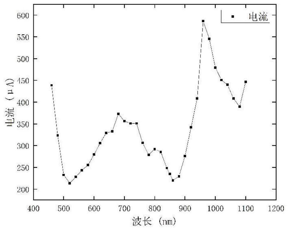
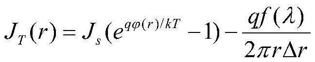
[0022] Depend on figure 1 As shown, the laser light source array is composed of a group of laser light sources with a certain wavelength. The wavelength of the laser light source is distributed in an arithmetic sequence, and the wavelength range is 400nm to 1100nm, and the wavelength tolerance is 20nm. The laser light source array is irradiated on the flexible photoelectric sensor to obtain the spectral response curve of the flexible photoelectric sensor, thereby obtaining the wavelength-current calibration result. Its theoretical formula is as follows:

[0023] The forward current is divided into two parts, one is the first part that can...


PUM

PropertyMeasurementUnit
wavelengthaaaaaaaaaa

Abstract

The invention provides a non-contact bridge displacement sensing method based on a flexible photoelectric sensor array, which is used to measure the deflection of the whole bridge in real time. The wavelength-current relationship is calibrated to the flexible photoelectric sensor, an array is formed of a plurality of flexible photoelectric sensors, and the flexible photoelectric sensor array is fixed on the lower surface of the bridge to be measured with the mid-span as the center of symmetry; The laser light source array is arranged on the end support of the bridge to be tested, the positions of all the laser light source are determined, and the outgoing light rays of the laser light source array are all parallel. The flexible photoelectric sensor receives the laser signal, outputs the corresponding induced current, locates the position of its light source according to the calibration result, and obtains the deflection of the point to be measured according to the calculation formula. Compared with other traditional deflection measurement devices, the non-contact bridge displacement sensing method based on the flexible photoelectric sensor array has the advantages of simple structure, high measurement accuracy, fast response speed, wide application range, and real-time multi-measuring point sensing.

Description

technical field [0001] The invention relates to a non-contact bridge displacement sensing method based on a flexible photoelectric sensor array. Background technique [0002] The deflection and deformation of the bridge is an important parameter for the evaluation of the health status of the bridge, and an important index for the bridge inspection test and health monitoring. The deflection test is also widely used in bridge engineering. The bridge deflection detection is mainly to measure the deflection of the bridge span under the condition of dead load and live load, so it is necessary to accurately measure the static and dynamic deflection of the bridge. In modern bridge engineering, the commonly used beam deflection measurement methods mainly include dial indicator measurement method, precision level measurement method, total station measurement method, connecting pipe measurement method, differential GPS observation method, etc. The dial gauge measurement method is to ...

Claims


Application Information

Patent Timeline
Patent Type & Authority Patents(China)
IPC IPC(8): G01B11/02G01B11/16
CPCG01B11/02G01B11/16
Inventor 张鹤沈昕昳周煜辉
Owner ZHEJIANG UNIV
Why Eureka
Try Eureka