Shell, preparation method of shell and electronic device with shell

A technology of shell and powder materials, which is applied in the direction of electrical equipment shells/cabinets/drawers, electrical components, casings/cabinets/drawer parts, etc., can solve the problem of insufficient surface hardness and overall strength of plastic shells, resistance Poor drop performance, difficulty in forming 3D structures, etc.

Inactive Publication Date: 2020-06-05
FIH PRECISION ELECTRONICS LANG FANG CO LTD
View PDF5 Cites 4 Cited by
  • Summary
  • Abstract
  • Description
  • Claims
  • Application Information

AI Technical Summary

Problems solved by technology

[0002] With the advent of the 5G communication era, all-metal mobile phone back shells will be abandoned by mobile terminals due to interference with antenna signals. Non-metallic materials such as plastics, composite plates, glass, and ceramics have little interference with antenna signals, but plastics , Composite plates are difficult to endow products with high-end, atmospheric and stable temperament, and cannot reflect the added value of products. The overall strength of glass and ceramic materials has not yet reached the level of application as the core mechanism (middle frame/integrated rear shell) of electronic products.
In response to the above problems, the industry currently mainly implements them through the selection of different materials and corresponding surface treatment processes, such as plastic materials with baking paint and in-mold decoration technology, glass and ceramic materials with grinding and polishing, printing, and physical vapor deposition (PVD) processes. There are some problems, such as: (1) Defects in the plastic material process: a. After the plastic material is molded, it needs to be painted or printed for many times to meet the requirements for appearance and reliability;

Method used


Image

  • Shell, preparation method of shell and electronic device with shell
  • Shell, preparation method of shell and electronic device with shell
  • Shell, preparation method of shell and electronic device with shell

Examples


Embodiment approach 1

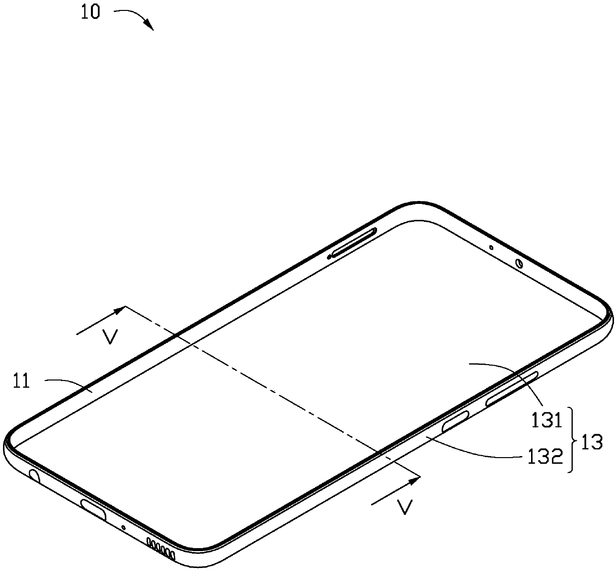
[0048] Please refer to Figure 8A , the second housing 13 includes a composite material layer 132 and a fiber layer 134 stacked on the composite material layer 132. Wherein, the composite material layer 132 serves as an appearance surface of the casing 10 .

Embodiment approach 2

[0050] ginseng Figure 8B , the second shell 13 includes two composite material layers 132 and a fiber layer 134. The fiber layer 134 is located between the two composite material layers 132 .

Embodiment approach 3

[0052] ginseng Figure 8C , the second shell 13 includes two composite material layers 132 and two fiber layers 134. The two composite material layers 132 and the two fiber layers 134 are successively stacked at intervals. Wherein, the composite material layer 132 away from the first casing 11 serves as the appearance surface of the casing 10 .

[0053] Further, the second casing 13 also includes an appearance layer 15 . The appearance layer 15 is formed on the surface of the composite material layer 132 away from the first casing 11 .

[0054] see Figure 9A , Figure 9B with Figure 9C , the fourth preferred embodiment of the second housing 13. The second shell 13 includes at least one composite material layer 132 and at least one fiber layer 134.

[0055] In this embodiment, the at least one composite material layer 132 and the at least one fiber layer 134 are sequentially stacked at intervals to form the second shell 13. Wherein, the fiber layer 134 away from the f...


PUM


Abstract

A shell comprises a first shell body and a second shell body, the first shell body is annular, and the first shell body comprises an inner surface and an outer surface opposite to the inner surface; and the second shell comprises a peripheral wall, the peripheral wall is arranged on the outer surface of the first shell in a sleeving mode, the second shell is of a composite structure and comprisesat least one composite material layer, and each composite material layer comprises a single-layer or multi-layer stacked composite layer. The invention further provides a preparation method of the shell and an electronic device with the shell.

Description

technical field [0001] The invention relates to a casing, a method for preparing the casing and an electronic device with the casing. Background technique [0002] With the advent of the 5G communication era, all-metal mobile phone back shells will be abandoned by mobile terminals due to interference with antenna signals. Non-metallic materials such as plastics, composite plates, glass, and ceramics have little interference with antenna signals, but plastics , Composite plates are difficult to give products a high-end, atmospheric and calm temperament, and cannot reflect the added value of products. The overall strength of glass and ceramic materials has not yet reached the level of application as the core mechanism of electronic product shells (middle frame / integrated rear shell). In response to the above problems, the industry currently mainly implements them through the selection of different materials and corresponding surface treatment processes, such as plastic materia...

Claims


Application Information

Patent Timeline
IPC IPC(8): H05K5/02
CPCH05K5/0217
Inventor 熊毅欧武政王有财梁国强杨迎波张恒
Owner FIH PRECISION ELECTRONICS LANG FANG CO LTD
Why Eureka
Try Eureka