Synchronous rectification control system and control method for secondary side resonance active clamping flyback
A technology of synchronous rectification and synchronous rectifier tube, which is applied in the direction of control/regulation system, output power conversion device, DC power input conversion to DC power output, etc. It can solve the problem of large voltage ripple at the output terminal and reduce the voltage. Effects of waveform, loss reduction, accurate turn-on and accurate turn-off
- Summary
- Abstract
- Description
- Claims
- Application Information
AI Technical Summary
Problems solved by technology
Method used
Image


Examples
Embodiment 1
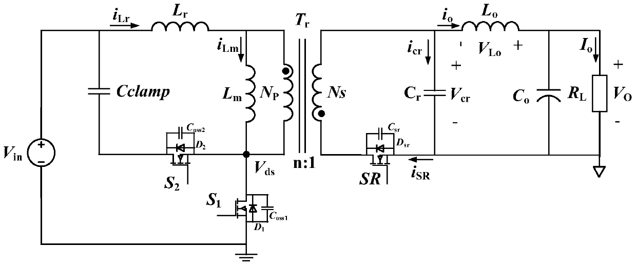
[0037] Example 1. The topology of a secondary resonant active clamp flyback converter in a preferred embodiment is as follows figure 2 As shown, the flyback converter includes: input DC voltage source V in , Transformer T r , Resonant inductance L r , Exciting inductance L m , Primary power tube S 1 , primary side clamp tube S 2 , clamp capacitor C clamp , main output circuit synchronous rectifier tube SR, secondary resonant inductor L o , Secondary side resonant capacitor C r , output filter capacitor C o , main load impedance R L , auxiliary output loop synchronous rectifier SR1, auxiliary load impedance R 1 .
[0038] Resonant inductance L r and magnetizing inductance L m can be regarded as a transformer T r part of which the resonant inductance L r Connect one end of the input DC voltage source V in of the positive terminal, the resonant inductance L r The other end is connected to the magnetizing inductance L m one end of the transformer T r One end of...
Embodiment 2
[0047] Example 2. The determination of the turn-on time and turn-off time of the synchronous rectifier SR in the main output loop of the secondary side resonant active clamp flyback converter belongs to two different periods, and the same detection hardware and control logic can be used, only at the time point difference. Therefore, the present invention proposes to use the first comparator 6 to determine the turn-on time of the synchronous rectifier SR of the main output loop, and to use the second comparator 9 to determine the turn-off time of the synchronous rectifier SR of the main output loop. A fixed first threshold voltage V is set to the first comparator 6 inside the microcontroller 5 th1 , set the second threshold voltage V for the second comparator 9 th2 .
[0048] By adopting the synchronous rectification control method of the secondary side resonant active clamp flyback proposed by the present invention, the setting of the state detection time period of the sync...
PUM
 Abstract
Description
Claims
Application Information
 - R&D
- Intellectual Property
- Life Sciences
- Materials
- Tech Scout
- Unparalleled Data Quality
- Higher Quality Content
- 60% Fewer Hallucinations
Browse by: Latest US Patents, China's latest patents, Technical Efficacy Thesaurus, Application Domain, Technology Topic, Popular Technical Reports.
© 2025 PatSnap. All rights reserved.Legal|Privacy policy|Modern Slavery Act Transparency Statement|Sitemap|About US| Contact US: help@patsnap.com