
Leading wire bonder

A wire bonding machine and body technology, which is applied to auxiliary devices, auxiliary welding equipment, welding/cutting auxiliary equipment, etc., can solve the problems of wire bonding points that are not close to objects, wear of rivet ends, and deformation of solder joints. Achieve the effect of increasing mass, reducing friction, and increasing smoothness

Active Publication Date: 2020-06-19
江苏微邦电子有限公司
View PDF9 Cites 2 Cited by
  • Summary
  • Abstract
  • Description
  • Claims
  • Application Information

AI Technical Summary

Problems solved by technology

[0003] The working principle of the existing wire bonding machine is as follows: Figure 4 As shown, the bonding wire is vertically inserted into the tool of the capillary capillary rivet, and the driving device drives the rivet to move downward. During the movement, the lead wire is heated into a liquid state under the action of the electric spark, and forms a spherical shape due to the effect of surface tension. Under the camera and precise control, the riving knife descends to make the ball touch the bonding area of ​​the wafer, pressurizes the ball, makes the ball and the pad metal form a metallurgical bond to complete the welding process, and then lifts the riving knife and moves along the predetermined track, called When the curved line reaches the second bonding point (pad), the pressure and ultrasonic energy are used to form a crescent-shaped solder joint. The vertical movement of the rivet cuts off the tail of the metal wire, and the lead is completed. During the use of the rivet, the During the wire bonding process, the thermocompression welding will apply pressure from the end face of the chopper, so that the lead wire and the pad metal will be pressed to produce a certain mutual plastic deformation and close contact, and their molecules will diffuse and bond firmly; ultrasonic welding will be generated by the transducer. Ultrasonic power makes the rivet vibrate, and produces ultrasonic frequency friction between the lead wire and the pad metal, removes the oxide layer on the interface, and causes elastic deformation. These two bonding principles will cause the force on the end face of the rivet to rub against the pad, After repeated welding, the end of the rivet is worn out, which leads to serious deformation of the solder joints. After repeated welding, the rivet will adhere to pollutant particles and partially damage them. If the point is not close to the object, there will be virtual welding and lead falling off. At the same time, the particles will also increase the wear of the riving knife, resulting in aging of the riving knife. Wire breakage or wire warping occurs, and at the same time, silicon and oxygen compounds are generated on the surface of the chopper during friction, resulting in breakage and burrs on the lead wire, which further affects the soldering of the chip

Method used


Image

  • Leading wire bonder
  • Leading wire bonder
  • Leading wire bonder

Examples


Embodiment Construction

[0018] The following will clearly and completely describe the technical solutions in the embodiments of the present invention with reference to the accompanying drawings in the embodiments of the present invention. Obviously, the described embodiments are only some, not all, embodiments of the present invention. Based on the embodiments of the present invention, all other embodiments obtained by persons of ordinary skill in the art without making creative efforts belong to the protection scope of the present invention.

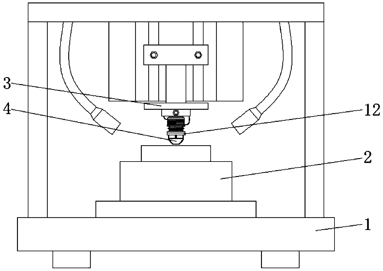
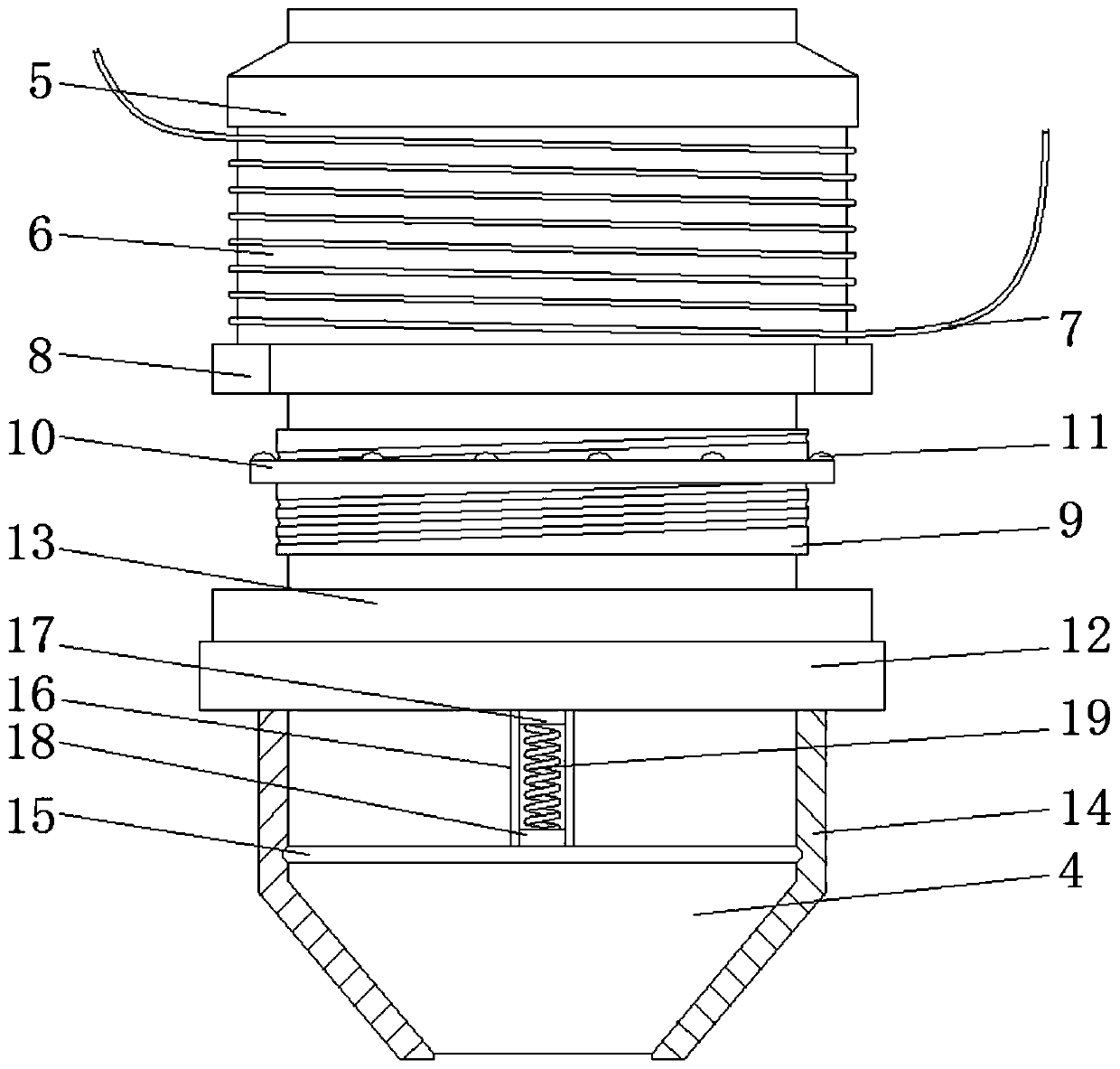
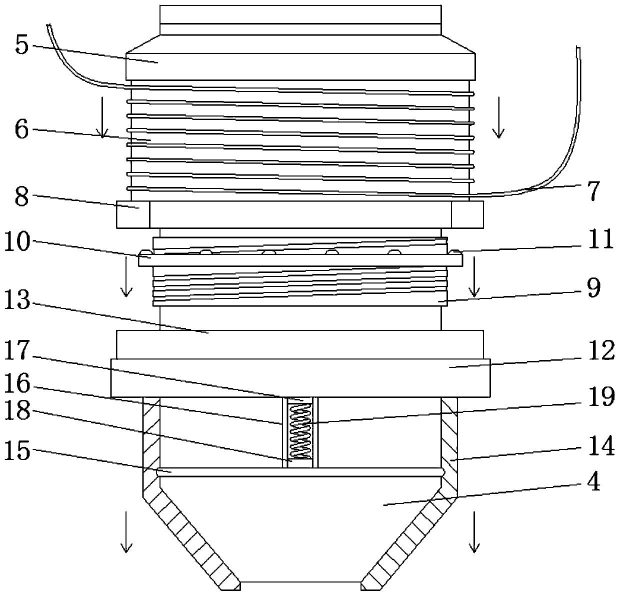
[0019] see Figure 1-3 , a wire bonding machine, comprising a machine body 1, a processing table 2, a driving device 3, and a rivet 4, the processing table 2 is installed on the body 1, the driving device 3 is installed on the inner wall of the body 1, and the riving knife 4 is installed on the drive At the bottom of the device 3, a sliding sleeve 5 is slidably installed on the splitting knife 4, and the sliding sleeve 5 can reciprocate on the splitting knife ...


PUM


Abstract

The invention relates to the technical field of semiconductor machining, and discloses a leading wire bonder. The bonder comprises a chopper, a sliding sleeve is slidingly mounted on the chopper, thebottom of the sliding sleeve is fixedly connected with an iron bar, the iron bar is wound with a wire, the end of the wire is connected with a power source in a driving device, the bottom of the ironbar is fixedly connected with an iron ring, an adjusting device is bonded on the chopper, through connection between the wire and the power source of the driving device, the running speed of the chopper is higher, the higher the speed is, the rapier the contact between the chopper and a welding disc is, the larger the friction coefficient is, the rapier the wear of the chopper is, the larger the generated current is, the larger the magnetic force generated by the iron ring is, through the principle of homopolar repulsion of a magnet, a magnetic block is ejected, a rubber cylinder moves downwards, the end of the chopper is covered, when the chopper makes contact with a welding disc each time, through elastic strength of the rubber cylinder, the contact area and the contact strength betweenthe chopper and the welding disc can be reduced, and friction between the chopper and the welding disc is reduced.

Description

technical field [0001] The invention relates to the technical field of semiconductor processing, in particular to a wire bonding machine. Background technique [0002] During the processing of semiconductors, wire bonding machines are often used to connect chips to circuit boards by wire bonding. [0003] The working principle of the existing wire bonding machine is as follows: Figure 4 As shown, the bonding wire is vertically inserted into the tool of the capillary capillary rivet, and the driving device drives the rivet to move downward. During the movement, the lead wire is heated into a liquid state under the action of the electric spark, and forms a spherical shape due to the effect of surface tension. Under the camera and precise control, the riving knife descends to make the ball touch the bonding area of ​​the wafer, pressurizes the ball, makes the ball and the pad metal form a metallurgical bond to complete the welding process, and then lifts the riving knife and m...

Claims


Application Information

Patent Timeline
Patent Type & Authority Applications(China)
IPC IPC(8): B23K28/00B23K37/00
CPCB23K28/00B23K37/00
Inventor 张拥银
Owner 江苏微邦电子有限公司
Learn More