Wet dicyandiamide pneumatic conveying device

A technology of wet material and pneumatic conveying of dicyandiamide, applied in the direction of conveying bulk materials, conveyors, transportation and packaging, etc., can solve the problems of poor fluidity, manpower dredging, time-consuming and labor-intensive, etc., so as to reduce production costs and simplify material transportation. Process, the effect of solving the material blockage of the pipeline

Inactive Publication Date: 2020-06-19
NINGXIA JIAFENG CHEMICALS CO LTD
View PDF5 Cites 2 Cited by
  • Summary
  • Abstract
  • Description
  • Claims
  • Application Information

AI Technical Summary

Problems solved by technology

[0003] The invention solves the problem in the prior art that the wet material of dicyandiamide is crystal particles with a certain viscosity, so whether it is during the feeding or the process of conveying, there will be a certain amount of material adhered to the wall of the feeding bin, and the conveying On the pipe wall, the fluidity is poor, and it often requires manpower to dredge, which is time-consuming and labor-intensive. A pneumatic conveying device for dicyandiamide wet material is provided. When it is applied, it uses the screw conveying at the outlet of the decanter screw machine in the dicyandiamide workshop and the drying bed. Height drop, install pneumatic valve, quantitative hopper, rotary feeding valve and material conveying pipeline at the bottom of the screw conveyor, through the power source of the Roots blower, through the heater, the hot air is sent to the direct blowing rotary valve, and the air volume Drive the suspended wet material into the conveying pipeline, and finally transport it to the dissolution kettle in the refining workshop, and heat and dissolve the material

Method used


Image

  • Wet dicyandiamide pneumatic conveying device
  • Wet dicyandiamide pneumatic conveying device

Examples


Embodiment

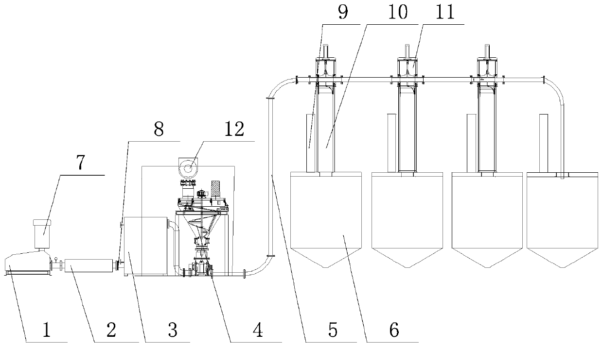
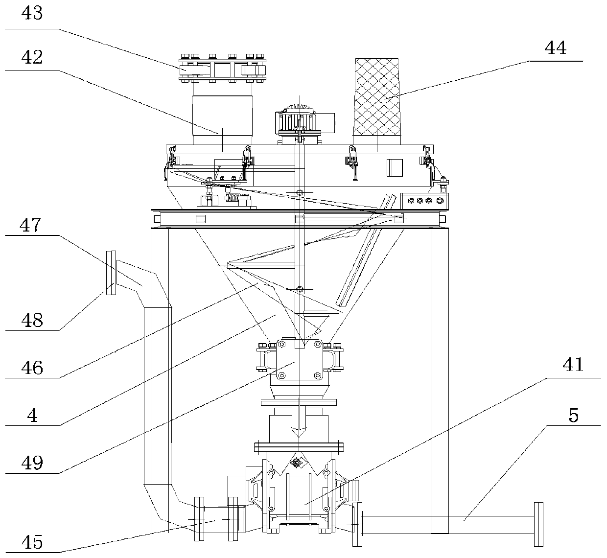
[0025] Such as Figure 1-2As shown, a dicyandiamide wet material pneumatic conveying device includes a Roots blower 1, a heater 3, and a quantitative silo 4. The outlet of the Roots blower 1 is provided with an outlet silencer 2, and the outlet silencer 2 is provided with an air outlet 8, the air outlet 8 is connected with the heater 3, the top of the quantitative feed bin 4 is connected with the shaftless screw conveyor 12, and the top of the quantitative feed bin 4 is provided with a feed inlet 42. The feed port 42 and the shaftless screw conveyor 12 are connected by a pneumatic flapper valve A43, and the lower part of the quantitative silo 4 is provided with a pneumatic flapper valve B49, and the pneumatic flapper valve B49 is connected to the lower part The set direct blowing rotary feeding valve 41 is connected together, and the direct blowing rotary feeding valve 41 is connected with the air extraction pipeline 5 below, and the front end of the air extraction pipeline 5 ...


PUM


Abstract

The invention discloses a wet dicyandiamide pneumatic conveying device which comprises a Roots blower, a heater and a quantitative stock bin, wherein an outlet silencer is arranged at the outlet of the Roots blower; an air outlet is formed in in the outlet silencer and is connected with the heater; the upper part of the quantitative stock bin is connected with a shaftless screw conveyer; a feedinghole is formed in the top of the quantitative stock bin; a pneumatic gate valve B is arranged at the lower part of the quantitative stock bin and is connected with a direct blowing rotary feeding valve arranged at the lower part; the direct blowing rotary feeding valve is connected with an exhaust pipeline below; the front end of the exhaust pipeline is connected with a hot-blast air inlet pipe;the exhaust pipeline is connected with a dissolving kettle arranged on the rear; a discharging pipe and a warehouse top reversing valve are arranged between the exhaust pipeline and the dissolving kettle; and a warehouse top exhaust pipe is arranged on the top of the dissolving kettle. During the actual using process, the wet dicyandiamide pneumatic conveying device adopts the quantitative conveying method to solve the problems about material adhesion to a wall and unsmooth discharging and to also solve the problem that the material blocks the pipeline to enable the production process to be smooth.

Description

technical field [0001] The invention relates to the field of dicyandiamide production, in particular to a dicyandiamide wet material pneumatic conveying device. Background technique [0002] Dicyandiamide is an important fine chemical raw material, which can be used in medicine, dyes, coatings, pesticides, glass fibers, lubricants and flame retardants. The existing dicyandiamide production technology adopts lime nitrogen hydrolysis reaction, decalcification and filtration to obtain cyanamide, and then performs cyanamide polymerization, crystallization, filtration and drying to obtain dicyandiamide products. Dicyandiamide saturated aqueous solution content is 3.10wt% (20 ℃), 7.24wt% (40 ℃), 15.79wt% (60 ℃), 24.21wt% (75 ℃) at different temperatures, dicyandiamide is higher than At 80°C, it will decompose into gaseous ammonia and release it. The concentration of the saturated aqueous solution of intermediate cyanamide is about 44wt% at 15°C to 25°C, and it is completely misc...

Claims


Application Information

Patent Timeline
Patent Type & Authority Applications(China)
IPC IPC(8): F26B3/10F26B21/00B65G53/40B65G53/66B65G69/20C01C3/16
CPCB65G53/40B65G53/66B65G69/20C01C3/16F26B3/10F26B21/001F26B21/004
Inventor 马丁石少峰谢皓朱贵荣
Owner NINGXIA JIAFENG CHEMICALS CO LTD
Why Eureka
Try Eureka