Method and device for separating ethylene from refinery plant dry gas

A technology for refinery dry gas and ethylene, applied in the chemical industry, can solve the problems that are not suitable for direct treatment of refinery dry gas, complex refrigeration and heat exchange process, low ethylene concentration, etc., to avoid losses, low cooling load, The effect of increasing the condensing temperature

Active Publication Date: 2020-06-23
CHINA PETROLEUM & CHEM CORP +1
View PDF7 Cites 9 Cited by
  • Summary
  • Abstract
  • Description
  • Claims
  • Application Information

AI Technical Summary

Problems solved by technology

However, the ethylene concentration in the product obtained by this method is low, and it still needs to be sent to the ethylene plant for further purification. At the same time, the required operation of the reabsorption tower requires the introduction of a large amount of gasoline absorbent
[0009] To sum up, the ethylene separation process commonly used in industry requires cryogenic conditions, and the refrigeration and heat exchange processes are complicated and not suitable for direct treatment of refinery dry gas, while Oil absorption process for recovering refinery dry gas is mainly to obtain carbon dioxide enriched gas with low ethylene content from refinery dry gas as raw material for ethylene cracking, which is generally not suitable for refineries without supporting ethylene equipment. At the same time, oil absorption process It is also necessary to set up a reabsorption tower or a cold box-expander to reduce the loss of absorbent, and the process is more complicated

Method used


Image

  • Method and device for separating ethylene from refinery plant dry gas
  • Method and device for separating ethylene from refinery plant dry gas
  • Method and device for separating ethylene from refinery plant dry gas

Examples


Embodiment 1

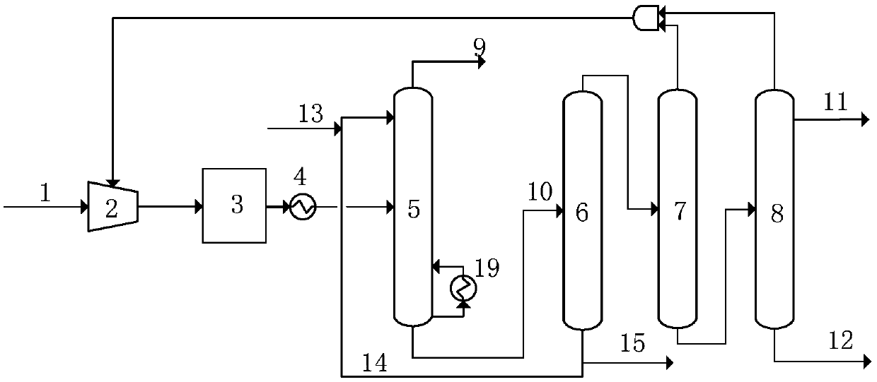
[0056] use as figure 1 Separation flow diagram shown for separation of ethylene from refinery dry gas.

[0057] The separation device includes a compressor 2, a purification unit 3, a cooler 4, an oil absorption tower 5, a depropanizer 6, a demethanizer 7, and an ethylene rectification tower 8; 4. The purification unit 3 and the oil absorption 5 are connected; the top of the oil absorption tower 5 is provided with a supplementary absorbent pipeline, the top of the tower is connected with the fuel pipe network, the tower kettle is provided with a reboiler 19, and the bottom of the tower is connected with the depropanizer 6; The top of the propane tower 6 is connected to the demethanizer 7, and the bottom of the tower is connected to the top of the oil absorption tower 5 and outside the boundary area; the top of the demethanizer 7 is connected to the second section of the compressor, and the bottom of the tower is connected to the ethylene distillation tower 8 ; The top of the ...

Embodiment 2

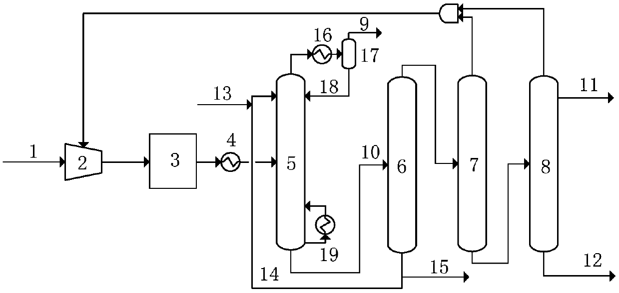
[0072] use as figure 2 Separation flow diagram shown for separation of ethylene from refinery dry gas.

[0073] The separation device includes a compressor 2, a purification unit 3, a cooler 4, an oil absorption tower 5, a depropanizer 6, a demethanizer 7, and an ethylene rectification tower 8; 4. The purification unit 3 and the oil absorption 5 are connected; the top of the oil absorption tower 5 is provided with a supplementary absorbent pipeline, a condenser 16 and a separation tank 17, and a reboiler is provided at the bottom; the top of the tower is connected with the condenser 16 and the separation tank 17 in turn , the top of the separation tank 17 is connected to the fuel pipe network, and the bottom of the tank is connected to the top of the oil absorption tower 5; the bottom of the oil absorption tower 5 is connected to the depropanizer 6; the top of the depropanizer 6 is connected to the demethanizer 7, and the bottom of the They are respectively connected to the ...


PUM


Abstract

The invention belongs to the field of chemical engineering, and particularly discloses a method and a device for separating ethylene from refinery plant dry gas. The method comprises the steps of compression, purification, cooling, absorption, propane removal, methane removal, and ethylene refining. The method is based on a shallow cold oil absorption technology, directly produces a polymer-gradeethylene product from refinery plant dry gas on the premise that the refrigeration process is simplified, the cold consumption is reduced and the investment is saved, and has great industrial application prospects.

Description

technical field [0001] The invention belongs to the field of chemical industry, and more specifically relates to a method and a device for separating ethylene from refinery dry gas. Background technique [0002] Refinery dry gas is an important resource of petrochemical industry, mainly from primary and secondary processing of crude oil, such as atmospheric and vacuum distillation, catalytic cracking (FCC), catalytic cracking (DCC), hydrocracking, delayed coking, etc., among which The amount of dry gas from catalytic cracking is the largest, generally accounting for 3%-5% of crude oil processing volume, which contains a large amount of light hydrocarbon resources such as hydrogen, methane, ethane, ethylene, propane, and propylene. At present, the annual processing capacity of domestic catalytic cracking units exceeds 200Mt, and the annual output of catalytic dry gas is above 6.0Mt, which contains 0.6-1.0Mt of ethylene. Most of the refinery dry gas is burnt as industrial and...

Claims


Application Information

Patent Timeline
Patent Type & Authority Applications(China)
IPC IPC(8): C07C7/00C07C7/04C07C7/11C07C7/09C07C11/04
CPCC07C7/005C07C7/04C07C7/11C07C7/09C07C11/04Y02P20/129
Inventor 张敬升廖丽华邵华伟罗淑娟刘智信胡志彦李东风
Owner CHINA PETROLEUM & CHEM CORP
Why Eureka
Try Eureka