
High-frequency high-voltage dynamic on-resistance test circuit and measurement method of switching device

A technology of on-resistance, high-frequency and high-voltage, which is applied in the field of electrical performance testing devices, can solve the problems of off-voltage limitation, long time required for stabilization, slow charging of capacitors, etc., achieve high off-voltage testing, improve test accuracy, Reasonable effect of the work process

Active Publication Date: 2020-06-26
润新微电子(大连)有限公司
View PDF8 Cites 6 Cited by
  • Summary
  • Abstract
  • Description
  • Claims
  • Application Information

AI Technical Summary

Problems solved by technology

To accurately measure the dynamic on-resistance of AlGaN / GaN HEMTs, it is necessary to test the dynamic on-state voltage drop. It is necessary to accurately measure the voltage signal whose amplitude is rapidly switched between less than 0.5V and hundreds of V. Such a fast signal requires Oscilloscope measurement requires a voltage probe that can withstand high voltage while achieving mV-level accuracy, which is difficult to achieve with current technology
[0004] Reference 1 (B.LuandT.Palacios, D.Risbud, S.Bahl, D.I.Anderson, "Extraction of Dynamic On-resistance in GaN Transistors under Soft-and Hard-switchingConditions," IEEE Compound Semiconductor Integrated Circuit Symposium, Nov, 2011.doi : 10.1109 / CSICS.2011.6062461.) can realize the measurement of the dynamic on-resistance by clamping the test point at high voltage, but there are also some shortcomings: first, the switch tube of the test branch needs to be a high-voltage MOS tube, and it needs to work online sex zone, difficult to control
Therefore, the circuit has certain limitations on the shutdown voltage applied by the device under test
Secondly, the switch tube of the test branch has a relatively large output capacitance. When the device under test is turned on, the charge stored in the output capacitance of the switch tube of the test branch will be released, and this part of the charge can only be released from the current through a small leakage current. released in the Zener diode, the entire release period will be extended
The voltage of the branch circuit is consistent with that of the main circuit, so the turn-on process of the device under test will be greatly delayed, and it is impossible to achieve fast switch test
[0005] Reference 2 (N.Badawi, O.Hilt, E.B.Treidel, J.Bocker, J.WiirflandS.Dieckerhoff,"Investigation of the Dynamic On-State Resistance of600VNormally-off and Normally-on GaN H EMTs," in IEEE Transactions onIndustryApplications , vol.52, no.6, pp.4955-4964, N ov, 2016.) Realized by using the diode in the test branch, the high voltage does not enter the detection end, thus realizing the clamping effect on the high voltage during the test and realizing the dynamic On-resistance measurement, but at the same time, there are certain deficiencies: First, the voltage at the test terminal is actually the sum of the voltage drop of the silicon carbide diode and the voltage drop of the device under test, and the current flowing through the silicon carbide diode is not constant. The difference in the voltage drop of the diode leads to a decrease in the measurement accuracy of the voltage drop of the device under test. In addition, the parasitic capacitance of the silicon carbide diode is large, and a large amount of heat is generated during high-frequency charging and discharging, which further reduces the calculation accuracy of its voltage drop.
Secondly, because the capacity of the capacitor in the test branch is relatively large, and the turn-off voltage of the device under test is often hundreds of volts, the resistance of the capacitor charging branch must withstand a high voltage. In order to meet the requirements of voltage division, its resistance must be high, loss
The resistance value of the capacitor charging branch is high and the loss is large, which has certain requirements for the current under the high voltage of the power supply. At the same time, it will cause the capacitor to charge slowly and take a long time to stabilize, making it difficult to achieve fast switching test

Method used


Image

  • High-frequency high-voltage dynamic on-resistance test circuit and measurement method of switching device
  • High-frequency high-voltage dynamic on-resistance test circuit and measurement method of switching device
  • High-frequency high-voltage dynamic on-resistance test circuit and measurement method of switching device

Examples


Embodiment Construction

[0031] It should be noted that, in the case of no conflict, the embodiments of the present invention and the features in the embodiments can be combined with each other. The present invention will be described in detail below with reference to the accompanying drawings and examples.

[0032] In order to make the purpose, technical solutions and advantages of the embodiments of the present invention clearer, the technical solutions in the embodiments of the present invention will be clearly and completely described below in conjunction with the drawings in the embodiments of the present invention. Obviously, the described embodiments It is only some embodiments of the present invention, but not all embodiments. The following description of at least one exemplary embodiment is merely illustrative in nature and in no way taken as limiting the invention, its application or uses. Based on the embodiments of the present invention, all other embodiments obtained by persons of ordina...


PUM


Abstract

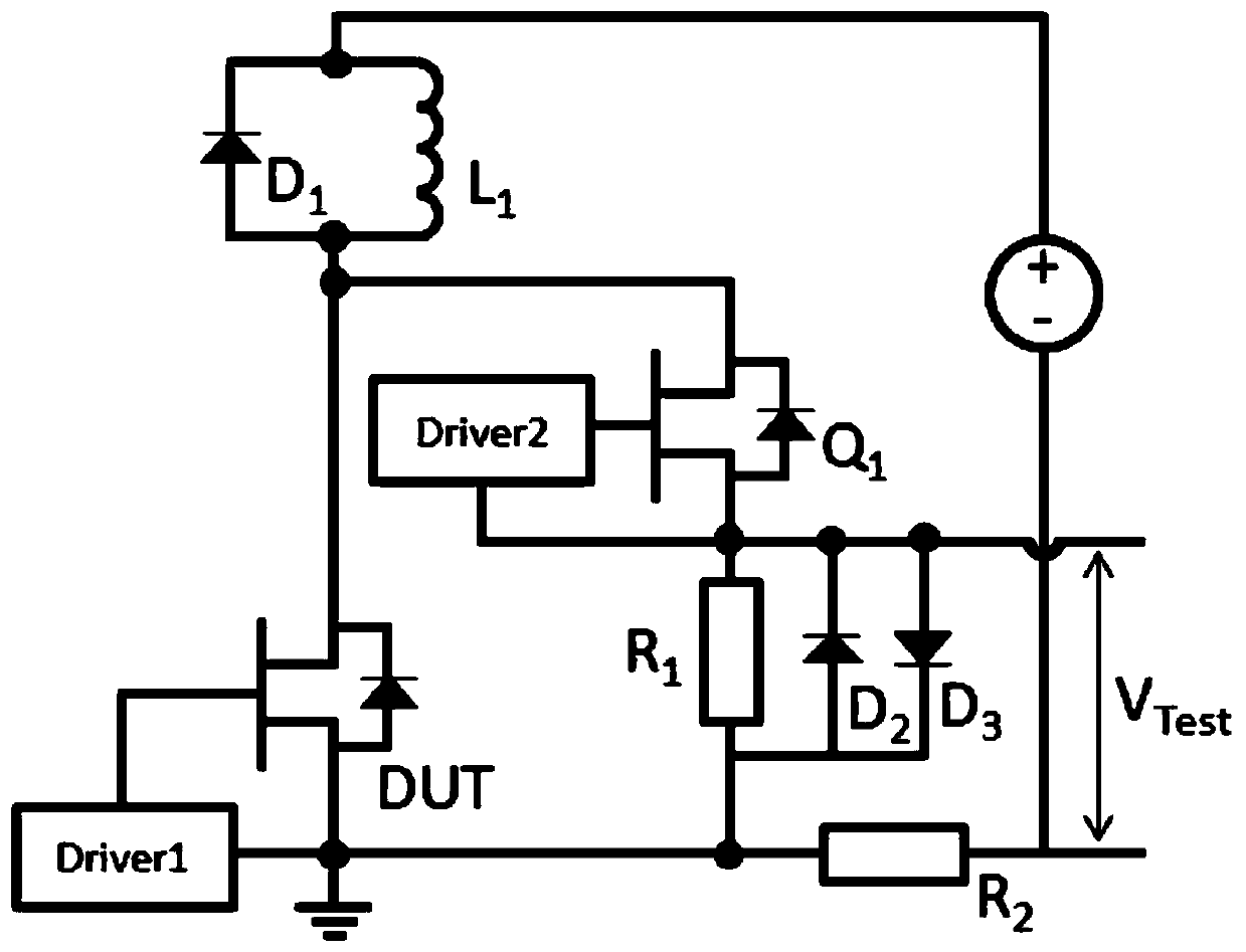
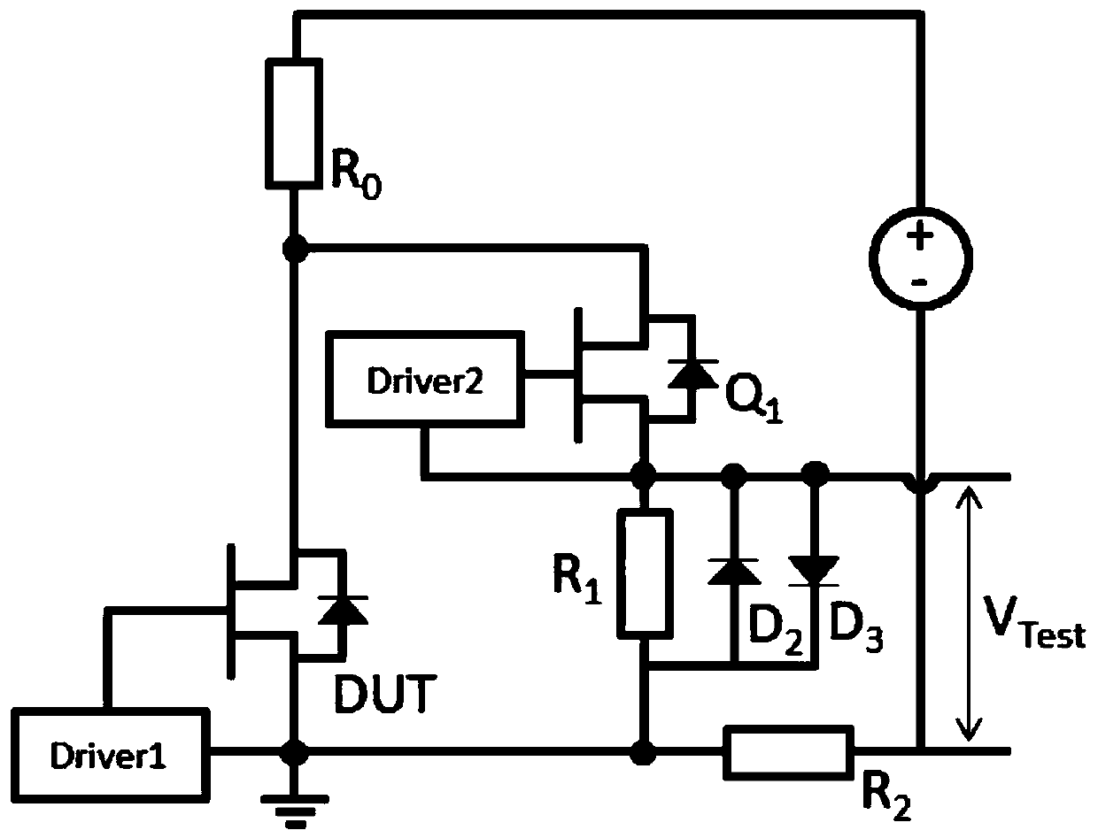
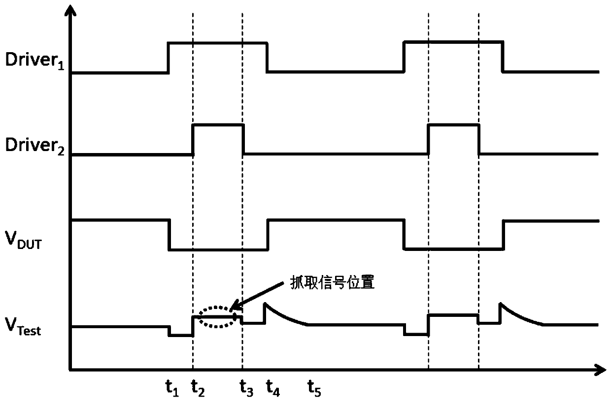
The invention provides a high-frequency high-voltage dynamic on-resistance test circuit and a measurement method of a switching device. The circuit comprises a main circuit and a test branch circuit,wherein the main circuit comprises a tested switching tube, a load, a current detection resistor and a power supply; a drain electrode of the tested switching tube is connected with the load in seriesand connected to a positive electrode of the power supply, and a source electrode of the tested switching tube is connected with the current detection resistor in series and connected to a negative electrode of the power supply; the test branch comprises a test switch tube and a test resistor; the drain electrode of the test switch tube is connected in series with the load and is connected to thepositive electrode of the power supply. The voltage of the test end is controlled by controlling the switching of the tested switching tube; when the tested switching tube is conducted, the voltage of the test end is the conduction voltage drop of the tested switching tube; when the tested device is turned off, the voltage of the test end is clamped at a low voltage. The new test method providedby the invention realizes high-voltage effective clamping, effectively reduces the voltage overshoot phenomenon caused by charging and discharging of an output capacitor, introduces a measurement branch of a zero-voltage zero-current switch, effectively improves oscillation and improves test precision.

Description

technical field [0001] The invention relates to an electrical performance testing device, in particular to a high-frequency and high-voltage dynamic on-resistance testing circuit and a measuring method of a switching device. Background technique [0002] The loss of the switching device is mainly reflected in the switching loss and conduction loss, among which the on-resistance directly affects the conduction loss, so the on-resistance is a core parameter of the switching device. As a third-generation semiconductor device, AlGaN / GaN high-mobility transistors (HEMTs) have many advantages, but due to the existence of high-density defects, trapping effects will occur under high electric fields, resulting in increased dynamic on-resistance. How to accurately characterize the dynamic on-resistance of switching devices, especially the dynamic on-resistance of AlGaN / GaN HEMT devices is very important. [0003] The increase of dynamic resistance of AlGaN / GaN HEMT is also related to...

Claims


Application Information

Patent Timeline
Patent Type & Authority Applications(China)
IPC IPC(8): G01R31/26G01R27/08G01R13/00
CPCG01R31/2637G01R27/08G01R13/00
Inventor 任永硕王荣华梁辉南高珺
Owner 润新微电子(大连)有限公司
Learn More