Production and processing device for composite coating

A processing device and cloth technology, which is applied to the device for coating liquid on the surface, metal processing, spraying device, etc., can solve the problems of slow speed, poor coating quality, affecting the production efficiency of composite coating, etc.

Pending Publication Date: 2020-07-03
桐乡市迪诺纺织股份有限公司
View PDF0 Cites 8 Cited by
  • Summary
  • Abstract
  • Description
  • Claims
  • Application Information

AI Technical Summary

Problems solved by technology

Most of the existing gluing methods use manual smearing, but there are many disadvantages in manually smearing paint on the cloth: 1. The speed of manual smearing is slow, which not only affects the production efficiency of composite coating, but also due to the smearing time Longer, the paint in the paint storage tank will change the uniformity of its various ingredients due to the longer time, and it will also solidify due to long-term non-flow and high temperature, which will affect the quality of paint and paint. Effect
2. The smearing quality of manual smearing is far worse than that of automatic mechanical smearing. Not only is it easy to produce uneven smearing, but also there will be cases of excessive smearing and missing coatings
3. The manual method requires a lot of manpower, which is less efficient than mechanical automatic equipment and increases production costs
In addition, after the paint is applied and heated and cured, the edge part of the cloth (also known as the waste edge) will have a poor coating effect, and it needs to be cut to ensure the integrity of the cloth, but generally cutting the waste edge requires manual operation. This will not only waste manpower, but also the odor generated when cutting the base cloth is harmful to the human body

Method used


Image

  • Production and processing device for composite coating
  • Production and processing device for composite coating
  • Production and processing device for composite coating

Examples


Embodiment Construction

[0033] The specific embodiments of the present invention will be described in further detail below with reference to the accompanying drawings and embodiments. The following examples are intended to illustrate the present invention, but not to limit the scope of the present invention.

[0034] The following references Figure 1 to Figure 7 The present invention will be described.

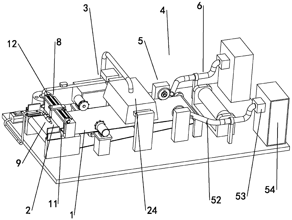
[0035] A production and processing device for composite coating, comprising a cloth transmission mechanism 1, a paint coating mechanism 2, a coating drying mechanism 3 and a trim cutting mechanism 4, and the paint coating mechanism 2 is arranged in front of the upper end of the cloth transmission mechanism 1. On the other hand, the coating drying mechanism 3 is arranged directly above the cloth conveying mechanism 1 , and the trim cutting mechanism 4 is arranged on both sides of the cloth conveying mechanism 1 and is located at the rear side of the coating drying mechanism 3 .

[0036] The paint c...


PUM


Abstract

The invention discloses a production and processing device for composite coating. The production and processing device comprises a cloth conveying mechanism, a paint coating mechanism, a coating drying mechanism and a leftover shearing mechanism, wherein the paint coating mechanism is arranged on the front side of the upper end of the cloth conveying mechanism, the leftover shearing mechanism is arranged on two sides of the cloth conveying mechanism and located on the rear side of the coating drying mechanism, the paint coating mechanism comprises a paint scraper, a spray gun moving mechanismand a paint spray gun assembly, the coating drying mechanism comprises a gas burner, a hot air chamber, a burning chamber and a drying cover, a cold air pipeline and a hot air outlet are arranged on the hot air chamber, an air intake fan is arranged on the cold air pipeline, a hot air channel is connected to the hot air outlet, the end, away from the hot air outlet, of the hot air channel is connected to the upper end of the drying cover, the drying cover is located right above the cloth conveying mechanism, and the far end, away from an air outlet hollow pipe, of an air delivery pipe is connected to the side wall of the cold air pipeline.

Description

technical field [0001] The invention relates to the technical field of composite coating production and processing, in particular to a composite coating production and processing device. Background technique [0002] Coating technology is a method of coating paste polymer, molten polymer or polymer melt on paper, cloth and plastic film to prepare composite material (film). [0003] Industrial coating is a process method in which a layer of glue, paint or ink with a specific function is applied on the surface of the substrate and dried. Most of the existing glue application adopts the manual application method, but there are many disadvantages when applying the paint on the cloth by manual operation: 1. The speed of manual application is relatively slow, which not only affects the production efficiency of composite coating, but also affects the production efficiency of composite coating due to the application time. For a long time, the paint in the paint storage bucket will ...

Claims


Application Information

Patent Timeline
IPC IPC(8): B05B16/20B05B13/04B05B13/02B05B15/00B05D3/04D06H7/06B26D7/18B26D1/15
CPCB05B13/0221B05B13/041B05B15/00B05B16/20B05D3/0413B05D3/0426B26D1/151B26D7/1863D06H7/06
Inventor 夏敏
Owner 桐乡市迪诺纺织股份有限公司
Why Eureka
Try Eureka