New energy automobile DC charger output regulation and control circuit and power supply protection control method

A new energy vehicle and charger technology, applied in electric vehicle charging technology, battery circuit devices, efficient vehicle charging, etc., can solve problems such as excessive current that affects the quality of voltage conversion, reduced dynamic response, and reduced conversion efficiency. Improve dynamic response, increase adjustment range, reduce the effect of noise

Inactive Publication Date: 2020-07-03
南京沃瑞新能源科技有限公司
View PDF0 Cites 1 Cited by
  • Summary
  • Abstract
  • Description
  • Claims
  • Application Information

AI Technical Summary

Problems solved by technology

[0003] The adjustment range of the input voltage and output voltage of the existing charger is small, thereby reducing the practical range of the charger, and the output voltage value of the transformer is adjusted many times, which will cause the output voltage of the transformer to change; audio noise will be generated in the transformer and inductor , and the audio noise will be transmitted along with the operation of components to affect other equipment, and at the same time reduce the dynamic response to changes in load and mains power, reducing the conversion efficiency; when the charger converts the input voltage into the output voltage, the output voltage cannot be maintained The stability of the lithium battery will increase the value of the current when the lithium battery has a large demand for the obtained voltage, causing the local temperature of the components to rise, affecting the quality of the voltage conversion and the current is too large; when the output voltage of the charger is adjusted, the output cannot be maintained. Stability of voltage and constant current

Method used


Image

  • New energy automobile DC charger output regulation and control circuit and power supply protection control method
  • New energy automobile DC charger output regulation and control circuit and power supply protection control method
  • New energy automobile DC charger output regulation and control circuit and power supply protection control method

Examples


Embodiment Construction

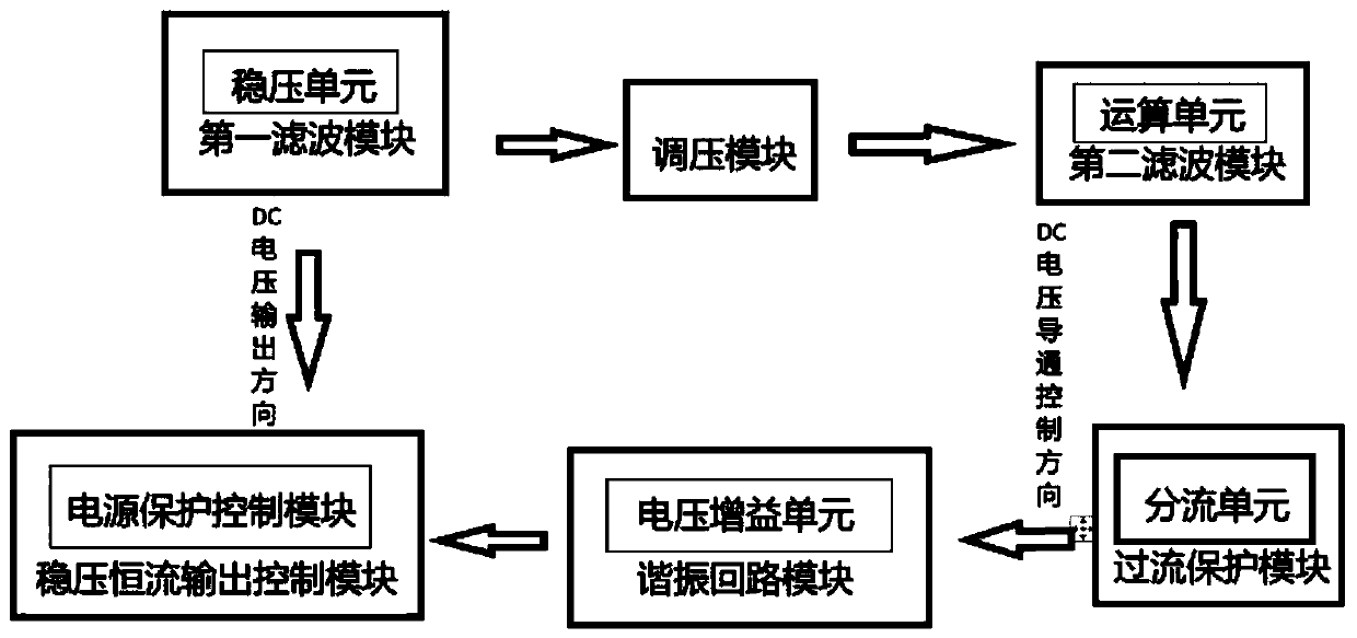
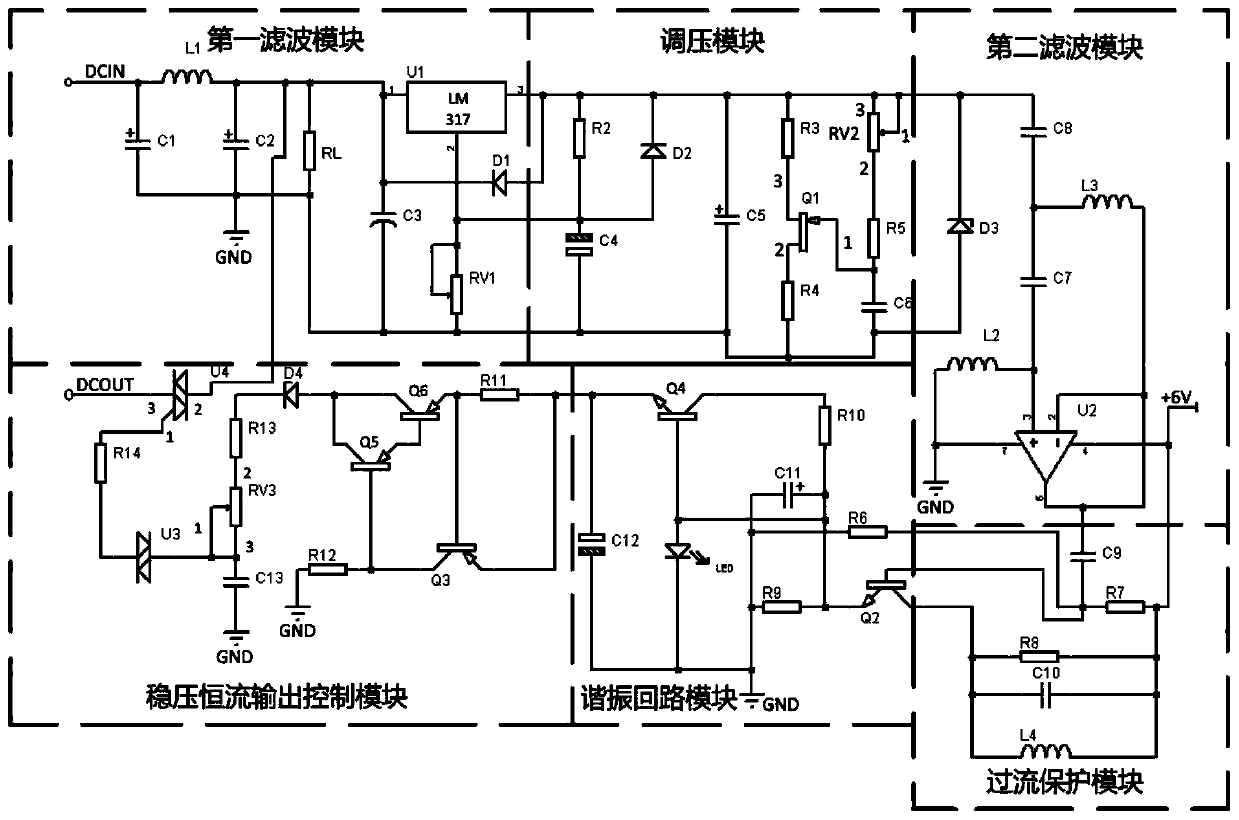
[0035] Such as figure 1 As shown, in this embodiment, a new energy vehicle DC charger output regulation circuit, including:

[0036] A first filter module for filtering the DC voltage converted by the charger to filter out ripples in the output voltage;

[0037] A voltage regulation module for adjusting the voltage obtained in the first filtering module, and then changing the output voltage value again;

[0038] A second filter module used to filter the regulated voltage signal to improve the stability of the secondary regulated output voltage;

[0039] An overcurrent protection module for detecting the current and voltage output by the second filter module, absorbing and storing high current;

[0040] A resonant circuit module used to obtain the output voltage in the overcurrent protection module, change the voltage conduction path through the triode to increase the resonant impedance, and then realize the voltage gain;

[0041] It is used to adjust the voltage and current...


PUM


Abstract

The invention discloses a new energy automobile DC charger output regulation and control circuit and a power supply protection control method. The circuit comprises a first filtering module, a voltageregulating module, a second filtering module, an over-current protection module, a resonance circuit module and a voltage stabilization constant-current output control module. An inductor L1 and a capacitor C1 in the first filtering module form a filtering circuit, and ripples in rectified output voltage are filtered out. A pin 1 of a variable resistor RV2 is moved in the voltage regulating module to change the resistance value of the resistor so as to reduce the passing voltage. An inductor L3 and an inductor L4 in the second filtering module are used for screening and filtering the adjustedelectric signals. A resistor R9 in the overcurrent protection module absorbs the electric energy stored in the capacitor C10 to prevent overlarge discharge current. A triode Q2 in the resonance circuit module controls voltage conduction to increase resonance impedance so as to realize voltage gain. A bidirectional silicon controlled rectifier U4 in the voltage stabilization constant current output control module receives an electric signal output by a charger through a pin 1 to realize voltage conduction so as to protect and control an output power supply.

Description

technical field [0001] The invention relates to the technical field of chargers, in particular to an output regulation circuit and a power supply protection control method of a new energy vehicle DC charger. Background technique [0002] The charger converts the received AC power into DC power through a transformer, or converts DC power into low-voltage DC power to meet the voltage requirements of the required electrical equipment. The charger uses a microprocessor as the processing control center to integrate complex hardware analog circuits. feedback to the microprocessor. [0003] The adjustment range of the input voltage and output voltage of the existing charger is small, thereby reducing the practical range of the charger, and the output voltage value of the transformer is adjusted many times, which will cause the output voltage of the transformer to change; audio noise will be generated in the transformer and inductance , and the audio noise will be transmitted along...

Claims


Application Information

Patent Timeline
Patent Type & Authority Applications(China)
IPC IPC(8): H02J7/00H02M3/00H02M3/04H02M1/14H02M1/15B60L53/00
CPCB60L53/00H02J7/0029H02J7/007H02M1/14H02M1/15H02M3/00H02M3/04Y02T10/70Y02T10/7072Y02T10/92Y02T90/14
Inventor 张彦磊
Owner 南京沃瑞新能源科技有限公司
Why Eureka
Try Eureka