Multi-stage heat exchange structure for deaerator

A technology of heat exchange structure and deaerator, which is applied in the direction of preheating, feed water heater, lighting and heating equipment, etc., and can solve the problem of low deaeration effect

Inactive Publication Date: 2020-07-07
张晓波
View PDF0 Cites 0 Cited by
  • Summary
  • Abstract
  • Description
  • Claims
  • Application Information

AI Technical Summary

Problems solved by technology

[0005] In order to solve the problem that the oxygen removal effect of the existing deaerator is far lower than the standard due to various factors in the actual production, the present invention provides a multi-stage heat exchange structure for the deaerator, the multi-stage heat exchange structure The core is that when the

Method used


Image

  • Multi-stage heat exchange structure for deaerator
  • Multi-stage heat exchange structure for deaerator
  • Multi-stage heat exchange structure for deaerator

Examples


Embodiment 1

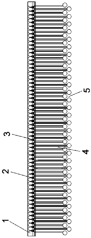
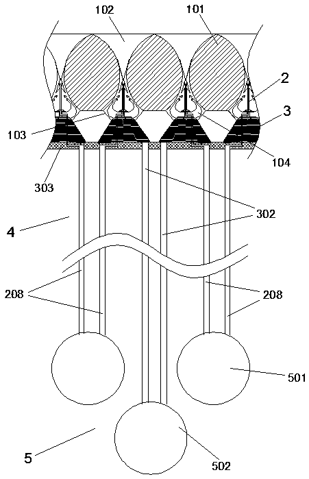
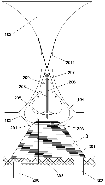
[0034] Such as Figure 1-5 As shown, a multi-stage heat exchange structure for a deaerator includes a water divider 1, and the water divider 1 includes a horizontally arranged water divider 101, and on the water divider 101 are distributed a number of water dividers that run through its thickness direction for The water distribution hole 102 for water guide, the section of each water distribution hole 102 is a hyperbolic shape, and the bottom of each water distribution hole 102 is provided with a rounded table-shaped gas collection cover 103 surrounding the water distribution hole 102, and the collection The air cover 103 cooperates with the lower part of the water distribution hole 102 to form the gas gathering cavity 104, and the gas jet assembly 2 is arranged in the gas gathering cavity 104, and the gas jet component 2 includes the first jet disc 201 and is arranged on the first jet via the connecting rod 206. The second air injection disk 207 on the disk 201, wherein the f...

Embodiment 2

[0041] This embodiment is an improvement made on the basis of Embodiment 1, and its basic structure is the same as that of Embodiment 1, the difference is that: figure 1 and 2 As shown, the fourth heat exchange area 5 is arranged below the water separator 1, and the fourth heat exchange area 5 includes a plurality of first steam branch pipes 502 arranged parallel to the water separator 101 and a layer parallel to the water separator 101. A plurality of second steam branch pipes 501 provided on the water dividing plate 101, and each first steam branch pipe 502 is correspondingly arranged below the middle position of the two second steam branch pipes 501, and the diameter of the first steam branch pipe 502 is greater than two The gap between the second steam branch pipes 501 forms a "herringbone" channel for water flow to pass through;

[0042] The water distribution holes 102 on the water distribution plate 101 are evenly distributed in rows, and each row of water distribution...

Embodiment 3

[0045] This embodiment is another improvement made on the basis of embodiment 1, and its basic structure is the same as that of embodiment 1, the difference is that: Figure 6 As shown, the water distributing hole 102 includes an upper outer expansion water area 1021, a middle narrow area 1022 and a bottom outer diffusion water area 1023, so that the deoxygenated water is steamed from bottom to top when passing through the narrow area 1022 Purge and disperse downward against the side wall of the outer diffusion water area 1023, improving the heating efficiency.


PUM


Abstract

The invention discloses a multi-stage heat exchange structure for a deaerator, and belongs to the field of thermal power generation. The multi-stage heat exchange structure comprises a water distributor, the water distributor comprises a water partition plate, wherein water distribution holes are densely distributed in the surface of the water partition plate, the cross section of each water distribution hole is in a two-curve shape, an inverted-cone-shaped gas collecting cover surrounding the water distribution holes is arranged at the bottom of each water distribution hole, each gas collecting cover is matched with the lower part of the corresponding water distribution hole to form a gas gathering cavity, a gas jet assembly is arranged in each gas gathering cavity and comprises a first gas jet disc and a second gas jet disc arranged on the first gas jet disc through a connecting rod, and an upward semi-annular steam flow along each water distribution hole is formed by using the corresponding gas jet disc, so that heating is conducted on deoxidized water entering each water distribution hole. The core of the multi-stage heat exchange structure is the water distribution holes in the water partition plate in a water distribution tank and the gas jet assembly arranged in each water distribution hole, and the special structure of each gas jet assembly is matched with the shape andstructure of the corresponding water distribution hole to form multiple heating and deaeration of the deoxidized water in the water distribution tank, so that the deaeration efficiency and the deaeration effect are improved.

Description

technical field [0001] The invention relates to the production of deoxygenated water in the field of thermal power generation, in particular to a multi-stage heat exchange structure for a deaerator. Background technique [0002] The deaerator is one of the key equipment of the boiler and heating system. If the deaerator has poor deoxygenation ability, it will cause serious losses to the corrosion of the boiler feed water pipe, economizer and other auxiliary equipment, and the economic loss caused will be the deaerator. Dozens or hundreds of times the cost of the oxygen generator. The main functions of the deaerator are as follows: one is to use the principle of thermodynamics to heat the feed water to the saturation temperature, and remove the dissolved gas in the feed water; the other is to increase the temperature of the feed water to improve the thermal cycle efficiency of the unit. [0003] At present, the deaerators equipped with large units include spray deaerators, r...

Claims


Application Information

Patent Timeline
IPC IPC(8): F22D1/30
CPCF22D1/30
Inventor 张晓波吴利峰张少帅张永飞陈康毅其他发明人请求不公开姓名
Owner 张晓波
Why Eureka
Try Eureka