Double-heat-source rotational flow flash calcining system and double-heat-source rotational flow flash calcining method

A dual heat source, calcination technology, applied in the direction of lighting and heating equipment, charge processing type, furnace components, etc., can solve the problems of complex equipment, energy consumption reduction, bulky, etc.

Pending Publication Date: 2020-07-07
JIANGSU ZHONGSHENGYUAN TECH CO LTD
View PDF1 Cites 0 Cited by
  • Summary
  • Abstract
  • Description
  • Claims
  • Application Information

AI Technical Summary

Problems solved by technology

At present, the technologies used for powder calcination in the world mainly include fluidized bed calcination process, swirl flow dynamic calcination process and suspension calcination process, but these processes have the following defects: complex and large equipment, high heat consumption, product quality control Difficulty, low product activity
However, due to the different properties of different powder materials, the same type of powder materials also have different compositions. Powder materials often show multi-stage decomposition of different substances during the calcination process. For example, the first stage of calcium carbide slag is the low temperature stage. Calcium hydroxide decomposition, the second stage is the decomposition of calcium carbonate in the high-temperature section, if the high-temperature calcination is performed in the flash calcination unit to complete the decomposition of these two stages, higher requirements will be placed on the material of the calcination unit, which will affect the equipment. service life, but also not conducive to reducing energy consumption

Method used


Image

  • Double-heat-source rotational flow flash calcining system and double-heat-source rotational flow flash calcining method
  • Double-heat-source rotational flow flash calcining system and double-heat-source rotational flow flash calcining method

Examples


Embodiment Construction

[0029] A specific embodiment of the present invention will be described below with reference to the accompanying drawings.

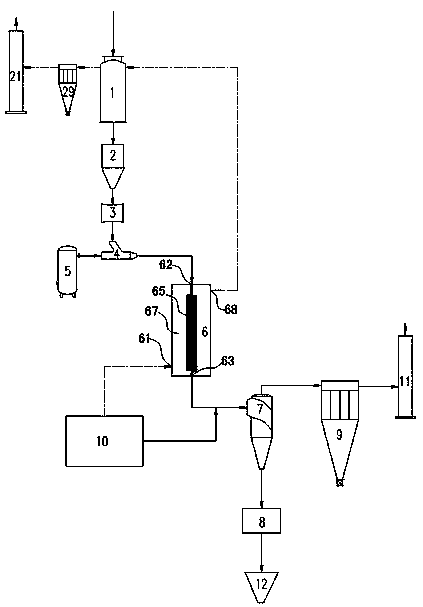
[0030] like figure 1 As shown, the dual heat source swirl flash calcination system according to a specific embodiment of the present invention includes a drying unit 1 for drying powder raw materials connected in sequence, a feeding bin 2, a rotary feeder 3 controlled by frequency conversion, a Venturi Inner feeder 4, flash calcination unit 6, cyclone secondary heating material collection unit 7, material cooling unit 8 connected to cyclone secondary heating material collection unit 7 and first flue gas treatment unit 9, hot blast stove 10, The first chimney 11, wherein the hot blast stove 10 is connected to the high-temperature flue gas inlet 61 of the flash calcination unit 6 to complete the first calcination reaction in the flash calcination unit 6, the first calcination reaction is calcium hydroxide decomposition reaction, Another road connects the ...


PUM


Abstract

The invention provides a double-heat-source rotational flow flash calcining system which comprises a drying unit, a discharging bin, a variable-frequency control rotary feeder, a Venturi feeder, a flash calcining unit and a cyclone secondary heating material collecting unit which are sequentially connected, and further comprises a material cooling unit, a first flue gas treatment unit and a hot blast stove. One path of the hot-blast stove is connected with a high-temperature flue gas inlet of the flash calcining unit to complete a first calcining reaction, the other path of the hot-blast stoveis connected with a material outlet of the flash calcining unit to complete a second calcining reaction, the Venturi feeder is connected with a pneumatic conveying unit, and the material cooling unitis connected with a bottom conical hopper. The invention further provides a double-heat-source rotational flow flash calcining method. The powder calcining time is short, powder calcining is sufficient and uniform, and calcined lime is high in activity; the energy consumption is low, the limitation of materials of the flash calcining unit is solved, the blocking problem of the flash calcining unit is avoided, and the service life of the flash calcining unit is prolonged.

Description

Technical field: [0001] The invention relates to a mineral calcination equipment and process, in particular to a dual heat source swirl flash calcination system and a dual heat source swirl flash calcination method. Background technique: [0002] Small materials produced in the mining process, slag produced in the production process, such as calcium carbide slag produced by calcium carbide furnace, slag after flotation of lead-zinc ore, desulfurized ash produced in the desulfurization process, etc., because the particle size of these materials cannot reach Calcination that is required but cannot be used in traditional crafts, there is a huge waste of resources, and it often has strong acidity and alkalinity, whether it is stacked in the open air or buried, it will cause serious pollution to the environment and endanger life and health of residents. [0003] In order to protect the environment and turn waste into wealth, it is necessary to carry out the necessary deep proces...

Claims


Application Information

Patent Timeline
Patent Type & Authority Applications(China)
IPC IPC(8): F27B19/04F26B21/14
CPCF26B21/14F27B19/04F27M2003/03F27M2003/16C04B2/10
Inventor 张林进庞焕军满毅沈浩赵波唐丹
Owner JIANGSU ZHONGSHENGYUAN TECH CO LTD
Why Eureka
Try Eureka