
Fuel cell metal bipolar plate

A metal bipolar plate and fuel cell technology, which is applied to fuel cells, fuel cell components, circuits, etc., can solve the problems of warping, reducing the flatness of bipolar plates, and easily breaking adhesives.

Active Publication Date: 2020-07-07
氢鑫沃德(上海)新能源发展有限公司
View PDF5 Cites 3 Cited by
  • Summary
  • Abstract
  • Description
  • Claims
  • Application Information

AI Technical Summary

Problems solved by technology

The cathode veneer has inlets and outlets for hydrogen, air, and coolant, and grooved oxygen channels; the anode veneer has inlets and outlets for hydrogen, air, and coolant, and grooved hydrogen channels; since the veneer is very thin, laser welding requires Strictly overlap and press two veneers, because there are many grooves and holes on the veneers, it is difficult to press and weld, and it is easily affected by the residual stress of stamping and welding, resulting in warpage OK, reduce the flatness of the bipolar plate; adopt the bonding method, the requirements for the glue are very high, because the fuel cell will have a certain temperature during operation, and the metal plate is in the process of thermal expansion and contraction, ordinary Glue breaks easily
[0005] These will cause the following problems: 1) the contact resistance between the membrane electrode and the bipolar plate, 2) the mechanical stability of the surface coating, which will affect the performance and life of the stack

Method used


Image

  • Fuel cell metal bipolar plate
  • Fuel cell metal bipolar plate
  • Fuel cell metal bipolar plate

Examples


Embodiment 1

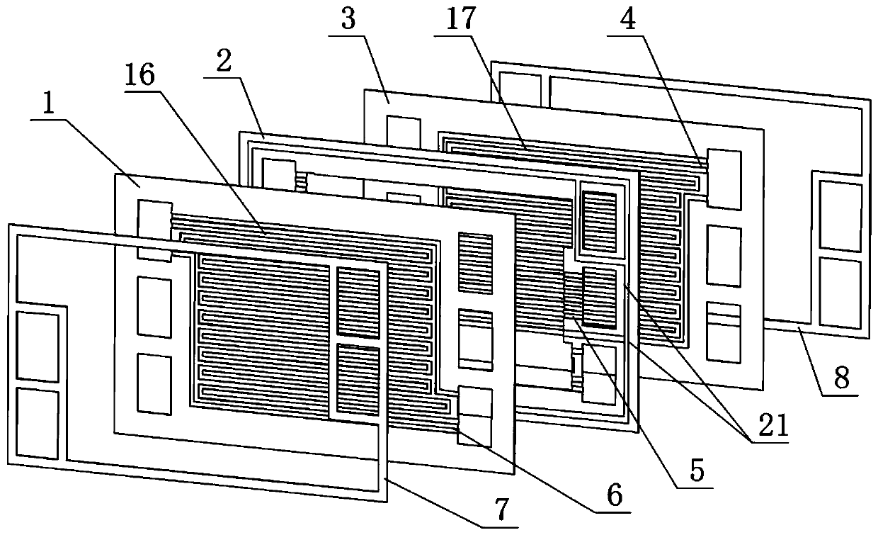
[0037] like figure 1 As shown, it is an exploded view of a metal bipolar plate, including a sealing gasket 7 , a cathode plate 1 , a gasket frame 2 , an anode plate 3 and a sealing gasket 8 arranged in sequence. The cathode plate 1 and the anode plate 3 are not provided with sealing grooves, and are sealed by the gasket 7 , the gasket 8 and the gasket frame 2 . The gasket a7 and the gasket b8 are in the shape of a square frame, and when the bipolar plate and the membrane electrode are assembled, they are sealed by the gasket.

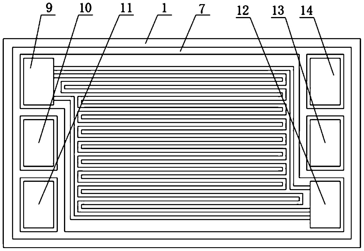
[0038] like figure 2 As mentioned above, it is a schematic diagram of the planar structure of the cathode plate. There are three inlets and three outlets on the board: oxidant inlet 9, oxidant drainage groove 6, oxidant outlet 12, fuel inlet 11, fuel drainage groove 4, fuel outlet 14, coolant inlet 10, Cooling liquid drainage groove 5, cooling liquid outlet 13, the positive side of the cathode plate 1 is provided with an oxidizing agent flow channel ...

Embodiment 2

[0044] like Figure 5 As shown, the coolant drainage groove 5 on the inside of the coolant inlet and outlet on the liner frame 2 selects a porous material 22 equivalent to the thickness of the liner frame, and the coolant enters from the coolant inlet 10 on the liner frame 2 through the porous material 22. The cooling liquid flow channel 17 enters the cooling liquid outlet 13 from the porous material on the other side and flows out.

[0045] The rest are the same as in Example 1.

Embodiment 3

[0047] like Image 6 As shown, the coolant drainage groove 5 on the inner side of the coolant inlet and outlet on the gasket frame 2 is made of a corrugated plate 23 with a thickness equivalent to the gasket frame, and the coolant passes through the corrugated plate 23 from the coolant inlet 10 on the gasket frame 2 into the cooling liquid flow channel 17, and then the porous material enters the cooling liquid outlet 13 and flows out from the other side. The front and back surfaces of the cathode plate and the anode plate have conductive anti-corrosion coatings, the coatings are sprayed after punching, and the coating materials are conductive anti-corrosion non-metallic materials.

[0048] The rest are the same as in Example 1.


PUM

PropertyMeasurementUnit
thicknessaaaaaaaaaa

Abstract

The invention relates to a fuel cell metal bipolar plate which comprises a cathode plate (1) and an anode plate (3) which are formed by stamping a single-layer metal sheet. A plurality of grooves punched in the front surface of the cathode plate (1) form an oxidant flow channel (16); protruding parts on the peripheries of the grooves form oxidizing agent flow channel walls. A plurality of groovespunched in the front face of the anode plate (3) form a fuel flow channel (18), wherein the protruding parts between the grooves form fuel flow channel walls; grooves are formed in the back faces of the protruding parts on the front faces of the anode plate (1) and the cathode plate (3) respectively, and back face protruding ridges are formed on the groove parts on the front faces respectively. The cathode plate (1) and the anode plate (3) are assembled in a back-to-back clinging manner, wherein the groove and the convex ridge on the back surface are coupled to form a groove-to-groove or groove-to-ridge cooling liquid flow channel (17). Compared with the prior art, the bipolar plate is compact in structure, ultrathin, good in conductivity, easy to process, low in cost, stable in structureand good in sealing performance.

Description

technical field [0001] The invention relates to a fuel cell, in particular to a fuel cell metal bipolar plate. Background technique [0002] A fuel cell is a device that directly converts the chemical energy of hydrogen and oxygen into electrical energy through an electrode reaction. A fuel cell is generally constructed of a plurality of cells, each cell comprising two electrodes (anode and cathode) separated by an electrolyte element and assembled in series with each other to form a fuel cell stack. The electrochemical reaction is achieved by supplying the appropriate reactants to each electrode, ie fuel to one electrode and oxidant to the other, creating a potential difference between the electrodes and thereby generating electrical energy. [0003] In order to supply each electrode with reactants, specific interface elements commonly referred to as "bipolar plates" and arranged on both sides of each individual cell are used. These bipolar plates are usually in the form ...

Claims


Application Information

Patent Timeline
Patent Type & Authority Applications(China)
IPC IPC(8): H01M8/0206H01M8/0258
CPCH01M8/0206H01M8/0258Y02E60/50H01M8/0228H01M8/026H01M8/0267
Inventor 高勇郑勤勇
Owner 氢鑫沃德(上海)新能源发展有限公司
Learn More