
A device for improving the resistance of tungsten carbide to knife edge

A cemented carbide and cutting edge technology, which is applied in the field of improving tungsten carbide cutting edge equipment, can solve the problems of poor cutting edge resistance, difficult to use, dust floating in the air, etc., and achieve the effect of reducing loss.

Active Publication Date: 2021-11-05
SHANDONG RUIXIN TUNGSTEN CO LTD
View PDF5 Cites 0 Cited by
  • Summary
  • Abstract
  • Description
  • Claims
  • Application Information

AI Technical Summary

Problems solved by technology

[0002] Cemented carbide is an alloy material made of hard compounds of refractory metals and bonding metals through powder metallurgy; it has a series of properties such as high hardness, wear resistance, good strength and toughness, heat resistance, and corrosion resistance. Excellent properties, especially its high hardness and wear resistance, remain basically unchanged even at a temperature of 500 ° C, and still have high hardness at 1000 ° C, but the existing tungsten carbide has disadvantages is less resistant to knife edge
[0003] In the prior art, compound carbides are added to the alloy for anti-knife edge. Before adding the compound carbides, the compound carbides need to be compacted and carbonized. Because the compound carbides are WC solid solution at high temperature The solid solution obtained by dissolving WC in TiC or WC in TiC-TaC (NbC) will have a large amount of dust floating in the air when it is compacted, and the compacted composite carbide has a certain temperature. Taking it out will increase the risk of workers' work and is not easy to use. Therefore, an improved tungsten carbide anti-knife edge equipment came into being.

Method used


Image

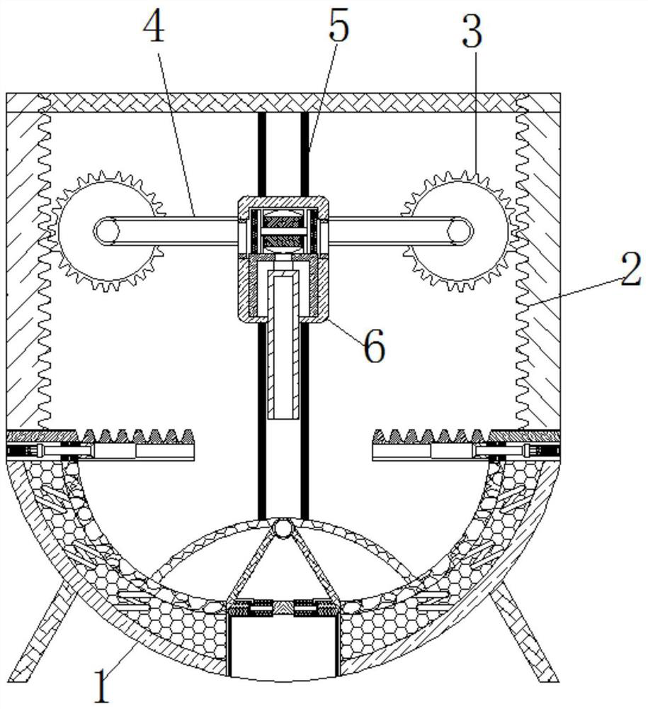
  • A device for improving the resistance of tungsten carbide to knife edge
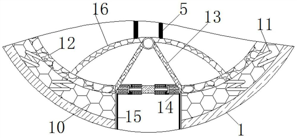
  • A device for improving the resistance of tungsten carbide to knife edge
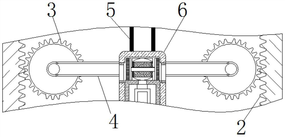
  • A device for improving the resistance of tungsten carbide to knife edge

Examples


Embodiment Construction

[0022] The following will clearly and completely describe the technical solutions in the embodiments of the present invention with reference to the accompanying drawings in the embodiments of the present invention. Obviously, the described embodiments are only some, not all, embodiments of the present invention. Based on the embodiments of the present invention, all other embodiments obtained by persons of ordinary skill in the art without making creative efforts belong to the protection scope of the present invention.

[0023] see Figure 1-6 , an improved tungsten carbide anti-knife edge device, including a housing 1, the bottom of the housing 1 is fixedly connected with feet, the feet are made of metal, and have heat insulation capabilities, the inner side walls of the housing 1 are both The tooth plate 2 is fixedly connected, and the surface of the tooth plate 2 is movably connected with the gear 3. The teeth on the surface of the tooth plate 2 are compatible with the toot...


PUM


Abstract

The invention relates to the technical field of hard alloy anti-knife edge, and discloses an improved tungsten carbide anti-knife edge device, which includes a casing, and the inner side walls of the casing are fixedly connected with tooth plates. The surface of the tooth plate is movably connected with a gear, and the surface of the gear is movably connected with a connecting plate. There is a slide rail inside the housing and on the surface of the connecting plate. The bottom of the tooth plate is movably connected with an engaging plate, and the surface of the suction block A spring rod is movably connected, and the end of the spring rod far away from the suction block is movably connected with an air bag, and the inside of the air bag is movably connected with a compression spring, and the end of the compression spring far away from the air bag is movably connected with a pressure plate, and the surface of the pressure plate is movably connected with undulations pole. The deformation of the rear spring rod acts on the surface of the airbag, and the negative pressure space inside the airbag is destroyed to generate a suction force, which will be expressed from the suction block and suck the powder, so the compaction is achieved. When reducing the loss of composite carbide powder effect.

Description

technical field [0001] The invention relates to the technical field of hard alloy anti-knife edge, in particular to an improved tungsten carbide anti-knife edge equipment. Background technique [0002] Cemented carbide is an alloy material made of hard compounds of refractory metals and bonding metals through powder metallurgy; it has a series of properties such as high hardness, wear resistance, good strength and toughness, heat resistance, and corrosion resistance. Excellent properties, especially its high hardness and wear resistance, remain basically unchanged even at a temperature of 500 ° C, and still have high hardness at 1000 ° C, but the existing tungsten carbide has disadvantages Is the ability to resist edge tumor is poor. [0003] In the prior art, compound carbides are added to the alloy for anti-knife edge. Before adding the compound carbides, the compound carbides need to be compacted and carbonized. Because the compound carbides are WC solid solution at high...

Claims


Application Information

Patent Timeline
Patent Type & Authority Patents(China)
IPC IPC(8): B30B11/22B30B15/00B30B15/32B08B15/04
CPCB08B15/04B30B11/22B30B15/0005B30B15/0082B30B15/32
Inventor 王建富
Owner SHANDONG RUIXIN TUNGSTEN CO LTD
Learn More