Fluorescence detection device and detection method thereof

A fluorescence detection and photoelectric detection technology, applied in the field of fluorescence detection, can solve the problems that the fluorescence detection device cannot be used with the temperature control device, can not obtain more accurate detection results, and has less interference with the fluorescence intensity signal, so as to improve the efficiency of excitation light and avoid Effect of Assay Error and Repeatability, High Fluorescence Sensitivity, and Fluorescence Intensity

Pending Publication Date: 2020-07-10
杭州柏恒科技有限公司
View PDF5 Cites 1 Cited by
  • Summary
  • Abstract
  • Description
  • Claims
  • Application Information

AI Technical Summary

Problems solved by technology

[0003] Aiming at the following problems in the prior art: 1. The top detection type fluorescence detection device is far away from the sample substance to be detected, and the detection results are easily interfered by phenomena such as evaporation and condensation in the tube; 2. The fluorescence detection device cannot cooperate with the temperature when scanning at the bottom. The use of the control device makes it impossible to obtain more accurate detection results; the invention provides a fluorescence detection device and its detection method. The test tube carrying the sample substance to be detected is placed through the substrate, and the temperature control device and the reciprocating optical fiber arranged under the test tube are used. The scanning mechanism scans the side of the sample substance to be detected in the test tube to obtain a fluorescence intensity signal with better consistency and less interference

Method used


Image

  • Fluorescence detection device and detection method thereof
  • Fluorescence detection device and detection method thereof
  • Fluorescence detection device and detection method thereof

Examples


Embodiment 1

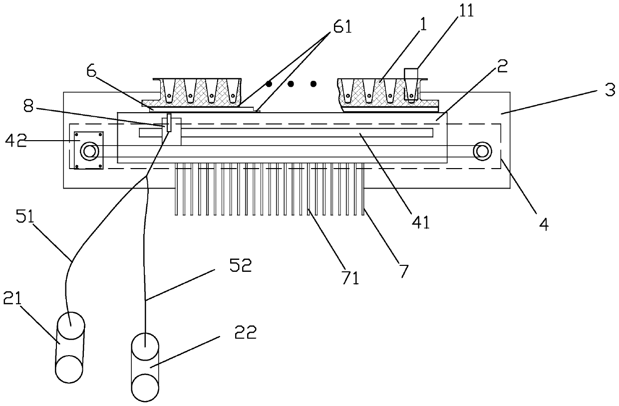
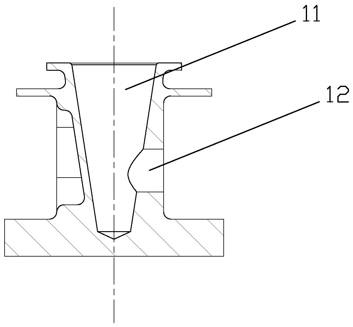
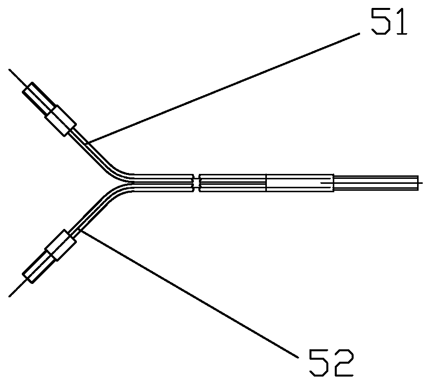
[0026] like figure 1As shown, a fluorescence detection device includes a base body 1 with a sample test tube placed inside and a base 3 provided with a photoelectric detection system 2. The photoelectric detection system 2 includes an excitation light module 21 and a fluorescence detection module 22. The detection system 2 also includes a reciprocating optical fiber scanning mechanism 4 disposed on the base 3, the reciprocating optical fiber scanning mechanism 4 is disposed on one side of the base body 1, and a detection hole 12 is provided on the base body corresponding to the side of the optical fiber scanning mechanism, The reciprocating optical fiber scanning mechanism 4 is connected to the excitation light module 21 and the fluorescence detection module 22 through the optical fiber 5 . The excitation light module is used to emit excitation light, so that the fluorescent components in the sample substance to be detected absorb light energy and enter an excited state, and t...


PUM


Abstract

The invention discloses a fluorescence detection device and a detection method thereof. The fluorescence detection device comprises basal bodies allowing a plurality of sample test tubes to be placed,a base provided with a photoelectrical detection system, and temperature controlling devices arranged between the base and the basal bodies, wherein the photoelectric detection system comprises an exciting light module and a fluorescence detection module, and further comprises a reciprocating optical fiber scanning mechanism arranged on the base, and the reciprocating optical fiber scanning mechanism is arranged on one side of the basal bodies; detection holes are formed in one side corresponding to the optical fiber scanning mechanism, in the basal bodies; and the reciprocating optical fiberscanning mechanism is connected with the exciting light module and the fluorescence detection module through optical fibers. The test tubes carrying sample substances to be detected are placed in thebasal bodies, and a motor drives the reciprocating optical fiber scanning mechanism to be in reciprocating movement to scan fluorescence of a detection reagent, so that improvement of exciting lightefficiency is facilitated, higher fluorescence sensitivity and higher fluorescence intensity are obtained, the fluorescence signal-to-noise ratio is increased, the temperature uniformity of a module is improved, and the cost is reduced.

Description

technical field [0001] The invention relates to the technical field of fluorescence detection, in particular to a fluorescence detection device and a detection method thereof. Background technique [0002] The polymerase chain reaction (PCR) is a molecular biotechnology that can amplify target DNA millions of times in a short period of time through denaturation, renaturation and extension. Real-time fluorescence quantitative PCR refers to adding fluorescent groups to the PCR reaction system, using the accumulation of fluorescent signals to monitor the entire PCR process in real time, and quantitatively analyzing the concentration of unknown templates through a standard curve. Now agriculture, medical and other industries are widely used in many fields. The current fluorescence detection device can be divided into two detection methods for the test tube carrying the product to be detected, namely top detection and bottom scanning. 1) Top detection, the main structure of the...

Claims


Application Information

Patent Timeline
Patent Type & Authority Applications(China)
IPC IPC(8): C12M1/34C12M1/38G01N21/64
CPCC12Q1/6851G01N21/6486B01L7/52C12Q2531/113C12Q2563/107
Inventor 吴保强马勇
Owner 杭州柏恒科技有限公司
Why Eureka
Try Eureka