
Liquid cooling dynamic heat management system for power supply

A dynamic thermal management, power battery technology, applied in secondary batteries, battery temperature control, circuits, etc., can solve the problems of limited heat exchange, difficult preheating function, uneven flow field, etc., to achieve intelligent control, The effect of avoiding energy loss and improving flexibility

Active Publication Date: 2020-07-10
HARBIN ENG UNIV
View PDF7 Cites 15 Cited by
  • Summary
  • Abstract
  • Description
  • Claims
  • Application Information

AI Technical Summary

Problems solved by technology

The heat management method of air-cooled power batteries is due to the small specific heat capacity of air, low thermal conductivity, small convective heat transfer coefficient, long time required for heat dissipation, poor cooling effect at high charge and discharge rates, and large inlet and outlet pressure differences of the entire system. Uneven, the difference in cooling conditions between the cells in the battery pack will lead to a large temperature difference in the battery pack, which has been gradually eliminated by the main engine factory
It is difficult to integrate heat dissipation and preheating functions in the direct cooling and heating management method, and the system complexity and cost are high
The thermal conductivity of phase change materials is low, the latent heat of phase change is small, and the amount of heat transfer is limited. It requires additional system volume and heavy weight, which greatly reduces the mass energy density and volume energy density of the entire thermal management system, and cannot dissipate heat in time. The problem of difficult preheating in thermal management of phase change materials is even more difficult to solve
Heat pipes and batteries have high requirements for shape adaptability, complex structures, poor heat transfer performance in tube structures, high insulation requirements, high processing technology requirements, and high costs. Phase change materials and heat pipe technologies still need a certain amount of time before industrial application

Method used


Image

  • Liquid cooling dynamic heat management system for power supply

Examples


Embodiment Construction

[0018] The present invention is described in more detail below in conjunction with accompanying drawing example:

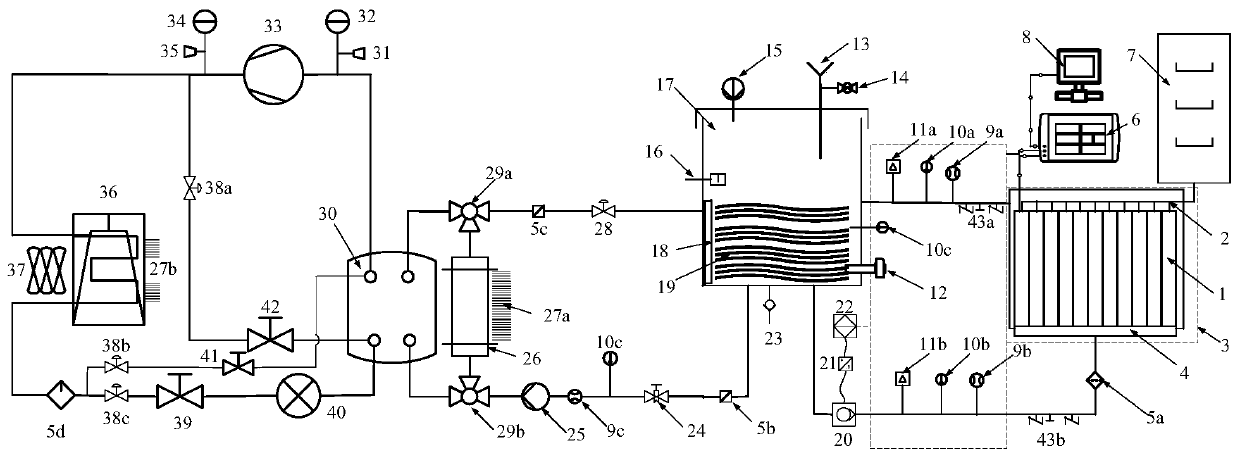
[0019] to combine figure 1 , a liquid-cooled dynamic thermal management system for a power battery, including a battery cell 1, a connecting row 2, a constant temperature and humidity box 3, a liquid cooling plate 4, dry filters 5a, 5b, 5c, 5d, a data collector 6, a charging and discharging Instrument 7, computer 8, flow sensor 9a, 9b, 9c, temperature sensor 10a, 10b, 10c, pressure sensor 11a, 11b, heater 12, filling funnel 13, filling regulating valve 14, liquid level sensor 15, liquid level Switch 16, liquid storage tank 17, thermal insulation cotton 18, coolant 19, external circulation pump 20, frequency converter 21, PLC controller 22, drain port 23, flow regulating valve 24, internal circulation pump 25, plate heat exchanger 26 , cooling fins 27a, 27b, manual valve 28, three-way reversing valve 29a, 29b, evaporator 30, low pressure protector 31, low pressure...


PUM


Abstract

The invention aims to provide a liquid cooling dynamic heat management system for a power battery. The system comprises a battery module, a liquid cooling plate, an outer circulating pump, a liquid storage tank, a multifunctional sensor, an inner circulating pump, a heater, a compressor, a condenser, an evaporator, a plate heat exchanger and a charging and discharging instrument, the system comprises a battery liquid cooling unit, a compressor unit refrigeration unit, a liquid cooling internal circulation unit, a liquid cooling external circulation unit, an environment simulation unit, a dataacquisition unit, a battery charging and discharging unit and the like. The multi-branch design can ensure that the system selects a proper heat management strategy to work according to the heat production power of the battery, dynamic monitoring and intelligent control of the whole power battery liquid cooling and heating management system are realized, and the energy consumption of the system can be greatly reduced.

Description

technical field [0001] The invention relates to a power battery thermal management system. Background technique [0002] With the increasingly prominent problems of energy security and environmental pollution in China, new energy vehicles have developed rapidly in recent years, and the entire automobile industry is transforming and upgrading in the direction of electrification and intelligence. It is self-evident that the performance of the core "three electric" components has an impact on the vehicle. In particular, the current power battery is developing in the direction of high energy density and short charging time. The high heat output of the power battery requires a thermal management system to dissipate heat quickly to ensure that the entire battery module or battery pack is in a suitable operating temperature range and the system is different. Location cell temperature uniformity. [0003] At present, the existing battery thermal management methods are mainly: air ...

Claims


Application Information

Patent Timeline
IPC IPC(8): H01M10/613H01M10/625H01M10/63H01M10/6567H01M10/6569
CPCH01M10/613H01M10/625H01M10/63H01M10/6567H01M10/6569Y02E60/10
Inventor 范立云李奎杰杨文翀徐舒航陈希
Owner HARBIN ENG UNIV
Learn More