Landslide foundation treatment embankment structure and construction method

A technology of embankment and foundation, which is applied in the direction of basic structure engineering, underwater structures, excavation, etc., can solve the problems of weak soil in the sliding layer losing strength, the sliding force of the landslide exceeds the anti-sliding force, and the load of the embankment cannot be reduced. Filling amount and filling load, land area, improvement of anti-sliding ability, and effect of reducing design section

Pending Publication Date: 2020-07-24
ZHEJIANG UNIV CITY COLLEGE
View PDF0 Cites 3 Cited by
  • Summary
  • Abstract
  • Description
  • Claims
  • Application Information

AI Technical Summary

Problems solved by technology

[0002] When building an embankment on a hillside foundation with a weak sliding layer, it is easy to cause landslides in the originally unstable strata due to the loading of the embankment. The water content is high. After the embankment is built, water seepage from the embankment and water accumulation on the slope will enter the sliding layer. When the precipitation is abundant, the drainage of the sliding layer is not smooth, resulting in the loss of strength of the weak soil in the sliding layer, and the loss of sliding resistance of the landslide.
The existing landslide treatment structures often use huge anti-slide piles to block landslides. Traditional scuppers can only seep water passively and cannot actively drain water. There is no way to reduce the embankment load. The above difficulties limit the construction of embankment structures in landslide strata. New treatment structure and construction method

Method used


Image

  • Landslide foundation treatment embankment structure and construction method
  • Landslide foundation treatment embankment structure and construction method
  • Landslide foundation treatment embankment structure and construction method

Examples


Embodiment Construction

[0044]The present invention will be further described below in conjunction with the examples. The description of the following examples is provided only to aid the understanding of the present invention. It should be pointed out that for those skilled in the art, without departing from the principle of the present invention, some improvements and modifications can be made to the present invention, and these improvements and modifications also fall within the protection scope of the claims of the present invention.

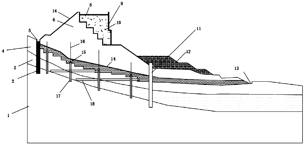
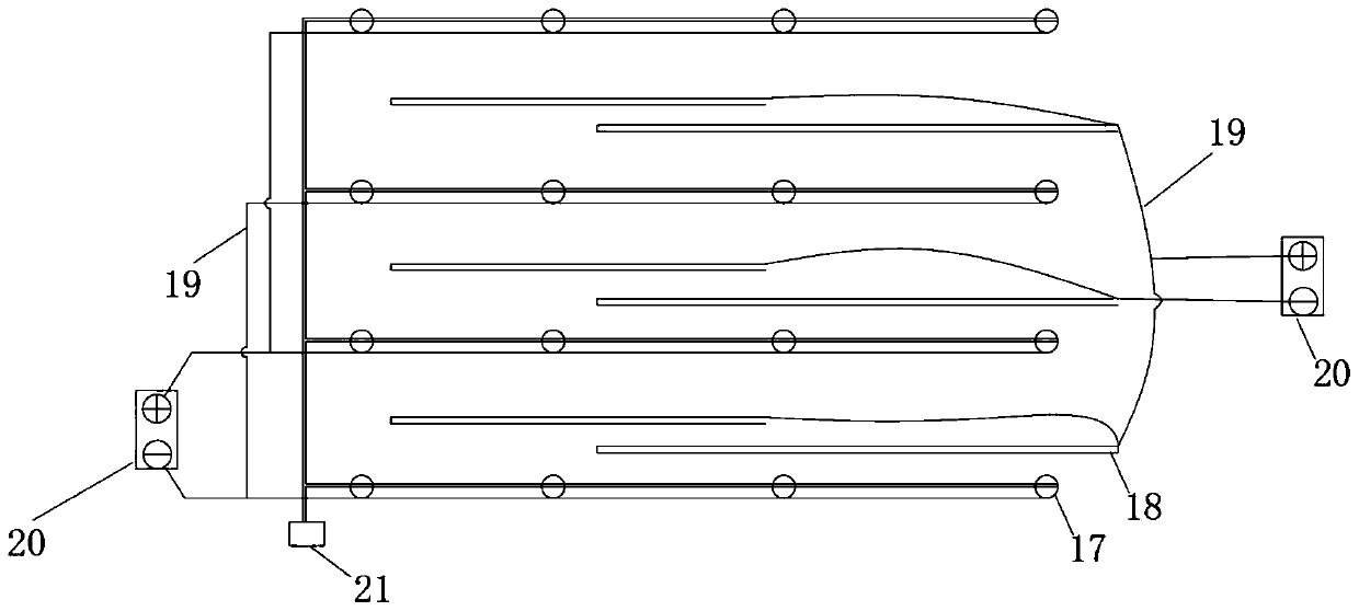
[0045] The landslide foundation treatment embankment structure includes bedrock 1, water cut-off curtain 2, weak sliding layer 3, foundation base 4, embankment fill 6, foam concrete embankment, anti-slide pile 11, back pressure berm 12, horizontal drainage pipe 17. Vertical drainage pipe 18.

[0046] A water-cutting curtain 2 is arranged at the top of the landslide, and a water-cutting ditch 5 is arranged on the top of the water-cutting curtain 2 . The water-cutt...


PUM


Abstract

The invention relates to a landslide foundation treatment embankment structure. The structure comprises a bed rock, a soft sliding layer, a foundation layer, embankment filling, anti-sliding piles, aloading berm, vertical water draining pipes and transverse water draining pipes. The weak sliding layer is mounted above the bed rock, the foundation layer is mounted above the weak sliding layer, a water cutting curtain is mounted on the top of a landslide, a catchwater is mounted on the top of the water cutting curtain, the vertical water draining pipes and the transverse water draining pipes are arranged in a landslide foundation, and are arranged in a row manner, the vertical water draining pipes are arranged vertically, the bottom ends of the vertical water draining pipes are embedded into the bed rock by a certain depth, outlets in the top ends of the vertical water draining pipes extend out of the foundation layer and are embedded in to a broken stone layer, the transverse water draining pipes are horizontal or outlets are inclined downwards by a certain angle, and the transverse water draining pipes are not embedded into the bed rock. The structure has the beneficial effects that through adoption of the water cutting, soft layer water draining, sliding resistance, load reducing and back pressure integrated treatment landslide foundation, the embankment structure is built, anti-sliding capacity of the landslide foundation embankment can be greatly improved.

Description

technical field [0001] The invention relates to an embankment structure, in particular to an embankment structure and a construction method for landslide foundation treatment, and belongs to the field of embankment engineering. Background technique [0002] When building an embankment on a hillside foundation with a weak sliding layer, it is easy to cause landslides in the originally unstable strata due to the loading of the embankment. The water content is high. After the embankment is built, water seepage from the embankment and water accumulation on the slope will enter the sliding layer. When the precipitation is abundant, the drainage of the sliding layer is not smooth, causing the weak soil in the sliding layer to lose its strength, and the landslide loses its sliding resistance. The existing landslide treatment structures often use huge anti-slide piles to block landslides. Traditional scuppers can only seep water passively and cannot actively drain water. There is no...

Claims


Application Information

Patent Timeline
Patent Type & Authority Applications(China)
IPC IPC(8): E02D17/20E01C3/00E02D3/10E02D19/18E03F5/04E02D29/02E02D31/02E02D5/34
CPCE01C3/00E02D3/10E02D5/34E02D17/20E02D17/207E02D19/18E02D29/02E02D31/02E03F5/04Y02A30/60
Inventor 王新泉崔允亮刁红国
Owner ZHEJIANG UNIV CITY COLLEGE
Why Eureka
Try Eureka