Laser energy amplifier

A laser energy and amplifier technology, applied in the field of lasers, can solve the problems such as the inability to effectively guarantee the quality of the output beam, the output quality of the output laser beam is degraded, and the nonlinear effect is small, and achieves maintenance-free beam quality, high repetition frequency, and stability. Good results

Pending Publication Date: 2020-07-31
福州市纳飞光电科技有限公司
View PDF0 Cites 3 Cited by
  • Summary
  • Abstract
  • Description
  • Claims
  • Application Information

AI Technical Summary

Problems solved by technology

[0003] At present, the typical amplification modes of laser amplifiers include fiber laser amplification and solid-state laser amplification, but these two different laser amplifiers have their own advantages and disadvantages: 1. Fiber laser amplifiers have small size, high integration, good stability, and maintenance-free And the advantages of good beam quality, and the fiber laser amplifier has a large surface-to-volume ratio, good heat dissipation performance, and small beam distortion caused by the thermo-optic effect, especially suitable for high-power laser output, but due to the limited mode field area of ​​the fiber, making it When the beam is transmitted in the optical fiber, it will produce serious nonlinear effects, which will lead to the deterioration of the output quality of the output laser beam; 2. The solid-state laser has a large mode field area, small nonlinear effects, and can output high pulse energy and peak power. However, in the process of high-power amplification, since the solid amplification medium is easily affected by thermal effects, the quality of the output beam cannot be effectively guaranteed, and its amplification gain is relatively low and its stability is poor.

Method used


Image

  • Laser energy amplifier
  • Laser energy amplifier
  • Laser energy amplifier

Examples


Embodiment Construction

[0038] Below in conjunction with accompanying drawing and specific embodiment the present invention is described in further detail:

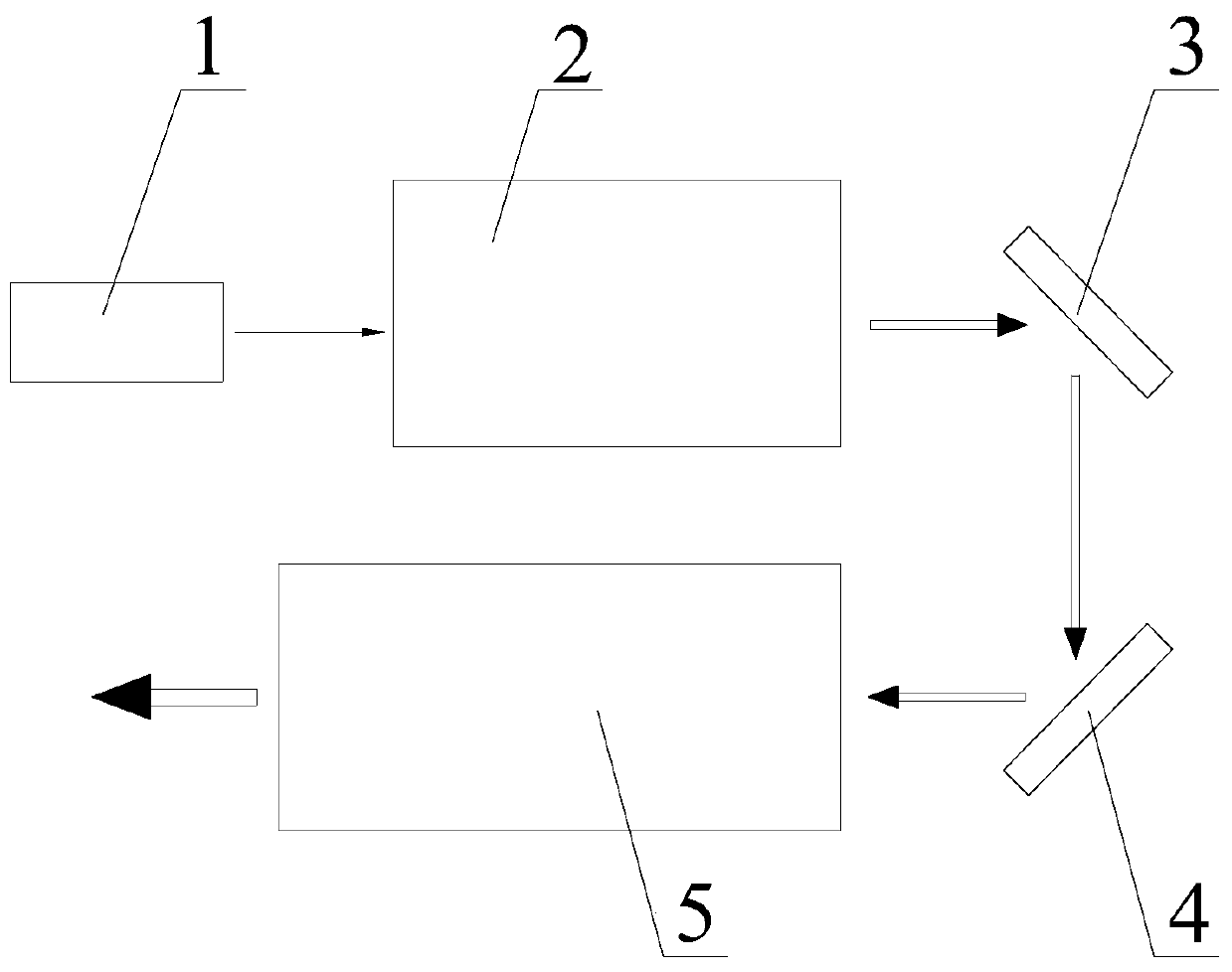
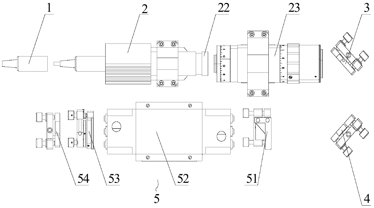
[0039] see Figure 1-7 As shown, a laser energy amplifier includes a signal laser seed source 1, a fiber laser amplification module 2, a first signal laser wavelength reflector 3, a second signal laser wavelength reflector 4, and a solid-state laser amplification module 5; the signal laser The seed source 1 is used to output the signal laser, including distributed feedback semiconductor laser (DFB), fiber laser seed source or solid laser seed source; the fiber laser amplification module 2 enhances and amplifies the weak signal laser output by the signal laser seed source 1 The output includes an all-fiber structure signal amplification module or a free space signal amplification module; the first signal laser wavelength reflector 3 and the second signal laser wavelength reflector 4 transmit the laser beam output by the fiber laser amplification ...


PUM


Abstract

The invention discloses a laser energy amplifier which comprises a signal laser seed source, an optical fiber laser amplification module, a first signal laser wavelength reflector, a second signal laser wavelength reflector and a solid laser amplification module. The signal laser seed source is used for outputting signal laser; the fiber laser amplification module amplifies and outputs weak signallaser output by the signal laser seed source, and comprises an all-fiber structure signal amplification module or a free space signal amplification module; and the first signal laser wavelength reflector and the second signal laser wavelength reflector transmit laser beams output by the fiber laser amplification module to the solid laser amplification module. The solid laser amplification modulecarries out secondary amplification on the input laser and then outputs the laser. The solid laser amplification module comprises a solid lath crystal semiconductor pump laser amplification module ora solid round bar crystal pulse xenon lamp pump laser amplification module. The multi-stage laser energy amplifying device is arranged, different stages can be combined and expanded according to needs, and weak signals can be subjected to laser amplification.

Description

technical field [0001] The invention relates to the technical field of lasers, in particular to a laser energy amplifier. Background technique [0002] With the continuous advancement of science and technology, more and more places need to use high-energy laser beams, but currently more single-mode lasers are used, due to their large cavity loss and small mode volume, their output energy is usually limited and cannot meet Require. In order to meet the requirements, it is necessary to use a laser amplifier to increase the output laser energy. The laser amplifier is a device that uses the stimulated radiation of light to amplify light energy. Through the laser amplifier, a higher laser energy can be obtained, and the output quality can also be maintained. laser beam. [0003] At present, the typical amplification modes of laser amplifiers include fiber laser amplification and solid-state laser amplification, but these two different laser amplifiers have their own advantages ...

Claims


Application Information

Patent Timeline
Patent Type & Authority Applications(China)
IPC IPC(8): H01S3/23H01S3/0933H01S3/0915
CPCH01S3/0915H01S3/0933H01S3/2375
Inventor 张江钿曹宇郑广建
Owner 福州市纳飞光电科技有限公司
Why Eureka
Try Eureka