
Landfill power plant leachate zero discharge method and system based on waste heat driving

A technology of landfill leachate and leachate, which is applied to the treatment of polluted groundwater/leachate, chemical instruments and methods, lighting and heating equipment, etc. Deal with difficult problems, reduce the steam production of incinerators, etc., to reduce workload, solve the problems of treatment and sewage discharge, and solve the effect of high operating costs

Pending Publication Date: 2020-08-04
TSINGHUA UNIV +1
View PDF6 Cites 0 Cited by
  • Summary
  • Abstract
  • Description
  • Claims
  • Application Information

AI Technical Summary

Problems solved by technology

[0002] Garbage power plants have become an important infrastructure for the consumption of urban garbage and biomass waste, and are currently being promoted on a large scale. However, it is difficult to treat the large amount of garbage leachate that exists. Currently, it is usually sent to a membrane concentration device after pretreatment. Concentration, the water production rate is usually only 40% to 60%, and the concentrated water is usually sprayed into the waste incinerator for vaporization, which often leads to combustion deterioration, especially greatly reduces the steam production of the incinerator, seriously affecting the power generation of the steam turbine, and running costs are high
The generation and discharge of other main process sewage in the plant, such as desalinated concentrated water, cooling tower sewage, flushing water, etc., are relatively large, resulting in a large waste of water resources

Method used


Image

  • Landfill power plant leachate zero discharge method and system based on waste heat driving

Examples


Embodiment 1

[0020] The specific embodiment 1 of the present invention is as follows.

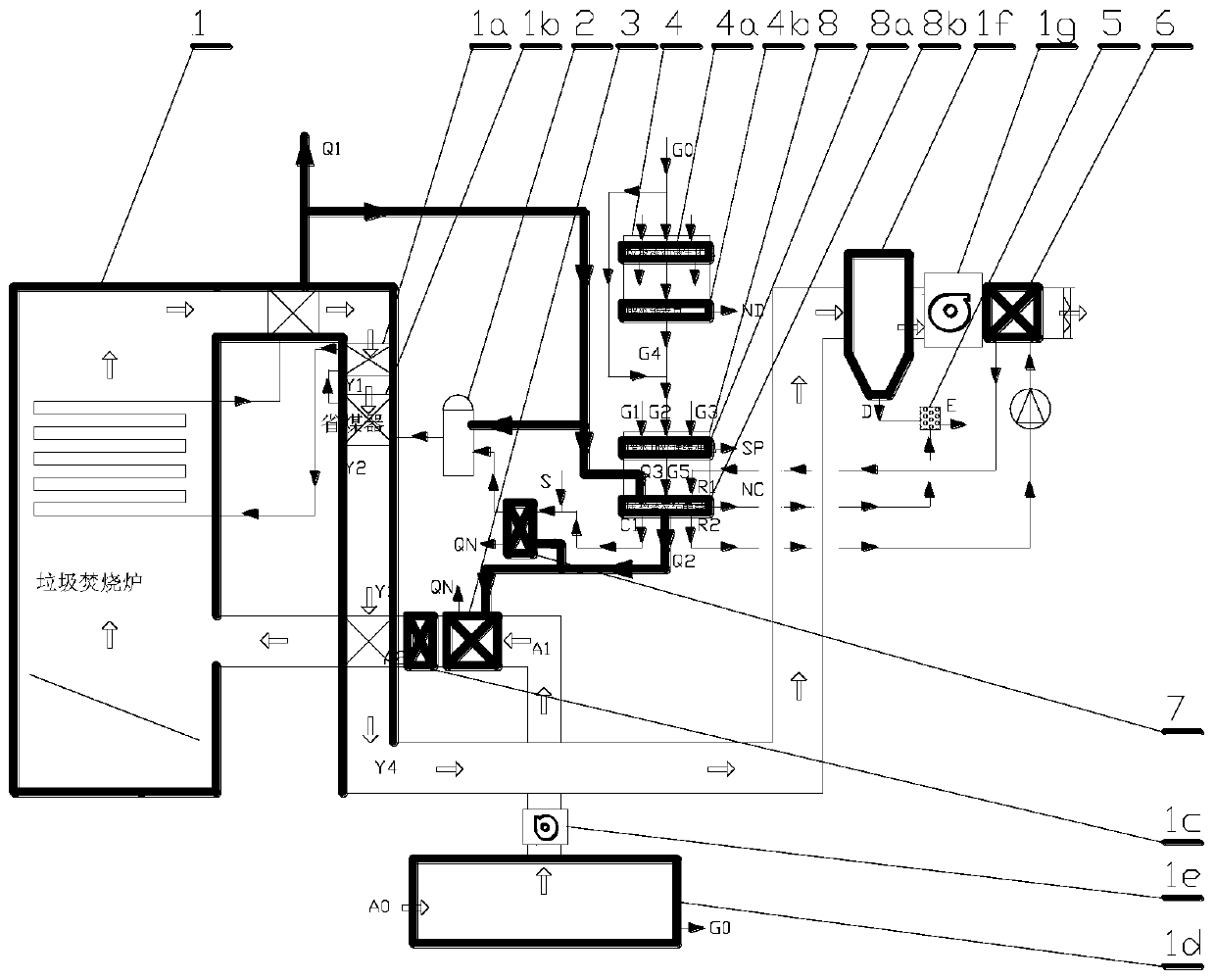
[0021] Waste heat-driven zero-discharge method and system for leachate from waste power plants, including pretreatment process of landfill leachate, waste heat evaporation concentration and crystallization process, waste heat recovery and utilization process of secondary steam, and utilization and disposal process of by-products, among which specific The process flow is as follows.

[0022] First, the leachate raw liquid G0 from the garbage fermentation tank 1d is sent to the main process sewage concentration module 4 for conventional biochemical treatment and membrane concentration, and the main process leachate discharge G4 is sent to the waste heat evaporation concentration crystallization module 8 to evaporate the waste water The pretreatment pool 8a, or the leachate stock solution G0 is directly sent to the waste water evaporation pretreatment pool 8a for pretreatment such as heavy metal reduction ...


PUM


Abstract

The invention discloses a landfill power plant leachate zero discharge method and system based on waste heat driving, and belongs to the technical field of garbage power generation and sewage zero discharge. For solving the problems that the steam yield, the stability of the combustion process in the incinerator and the like are seriously affected because garbage leachate of an existing garbage power plant is usually fed into an incinerator to be burnt out, a waste heat evaporator is adopted for evaporating and concentrating or crystallizing pretreated garbage leachate to produce salt, and a concentrated solution or crystallized salt and fly ash are solidified and buried; a driving heat source of the waste heat evaporator can be main steam or steam extracted by a steam turbine, and condensed water returns to a deaerator; the driving heat source can also be exhaust smoke high-temperature section waste heat recovered by adopting a low-low-temperature coal economizer; secondary steam obtained after sewage of the waste heat evaporator is evaporated is used for preheating boiler feed water in front of the deaerator or combustion-supporting air of the incinerator; the secondary condensedwater is used as raw water of desalted water or supplemented water of circulating water of a cooling tower; therefore, the heat energy used for evaporating the leachate is returned to the thermal process of the main process again, and the heat source cost is close to zero.

Description

technical field [0001] The invention relates to a method and system for zero discharge of leachate from a garbage power plant driven by waste heat, and belongs to the technical field of waste power generation and zero discharge of sewage. Background technique [0002] Garbage power plants have become an important infrastructure for the consumption of urban garbage and biomass waste, and are currently being promoted on a large scale. However, it is difficult to treat the large amount of landfill leachate. Currently, it is usually sent to a membrane concentration device after pretreatment. Concentration, the water production rate is usually only 40% to 60%, and the concentrated water is usually sprayed into the waste incinerator for vaporization, which often leads to combustion deterioration, especially greatly reduces the steam production of the incinerator, seriously affecting the power generation of the steam turbine, and Running costs are high. The production and discharg...

Claims


Application Information

Patent Timeline
Patent Type & Authority Applications(China)
IPC IPC(8): C02F9/10F22B33/18C02F103/06
CPCC02F9/00F22B33/18C02F1/44C02F1/04C02F1/00C02F2103/06C02F2301/08
Inventor 李先庭张茂勇赵健飞刘士刚韩志刚石文星王宝龙陈炜陈士强任淑颖岑俊平熊烽倪文岗
Owner TSINGHUA UNIV
Learn More