Small micro-bubble generator and method

A micro-bubble generator, a small technology, applied in the direction of ships, hydrodynamic characteristics/hydrostatic characteristics, hulls, etc., can solve the problems of high energy consumption, complex equipment, large equipment volume, etc., to achieve a simple and convenient control loop. The next time you use it, the device is small in size

Active Publication Date: 2020-08-14
NORTHWESTERN POLYTECHNICAL UNIV
View PDF11 Cites 7 Cited by
  • Summary
  • Abstract
  • Description
  • Claims
  • Application Information

AI Technical Summary

Problems solved by technology

Invention patent CN108341019A relates to a micro-bubble generator composed of an air intake pipe and hydrofoils. The air on the water surface is sucked into the hydrofoil through the air intake pipe to form bubbles. Part of the device needs to inhale air on the water surface, which is not suitable for underwater use. The use of aircraft; the invention patent CN105857511A relates to a micro-bubble generator composed of a water inlet pipe, an air inlet pipe, a blower, and a water pump. This device also needs to inhale air on the water surface, and the equipment is large in size and consumes a lot of energy, so it is not suitable for the use of underwater vehicles; the invention patent CN103861488A relates to a microstructure consisting of a water inlet pipe, a water pump, an air supply system, and an orifice plate. The bubble generator, through the water pump suction and air supply system, mixes water-air two-phase fluid to generate micro-bubbles through the orifice plate, but this device requires an additional air supply system, which is not conducive to the use of small underwater vehicles
Equipment that uses direct gas supply needs to absorb air from the water surface or carry equipment such as gas cylinders. The former generally requires a power source to absorb air, resulting in complex equipment, large volume, and high cost, and it is only suitable for flying objects on the water surface.
The latter can be applied to underwater vehicles, but the additional air source that needs to be carried is large, which also causes complex equipment and large volume, and is not suitable for the use of small underwater vehicles

Method used


Image

  • Small micro-bubble generator and method
  • Small micro-bubble generator and method
  • Small micro-bubble generator and method

Examples


Embodiment Construction

[0028] The embodiments described below by referring to the figures are exemplary and are intended to explain the present invention and should not be construed as limiting the present invention.

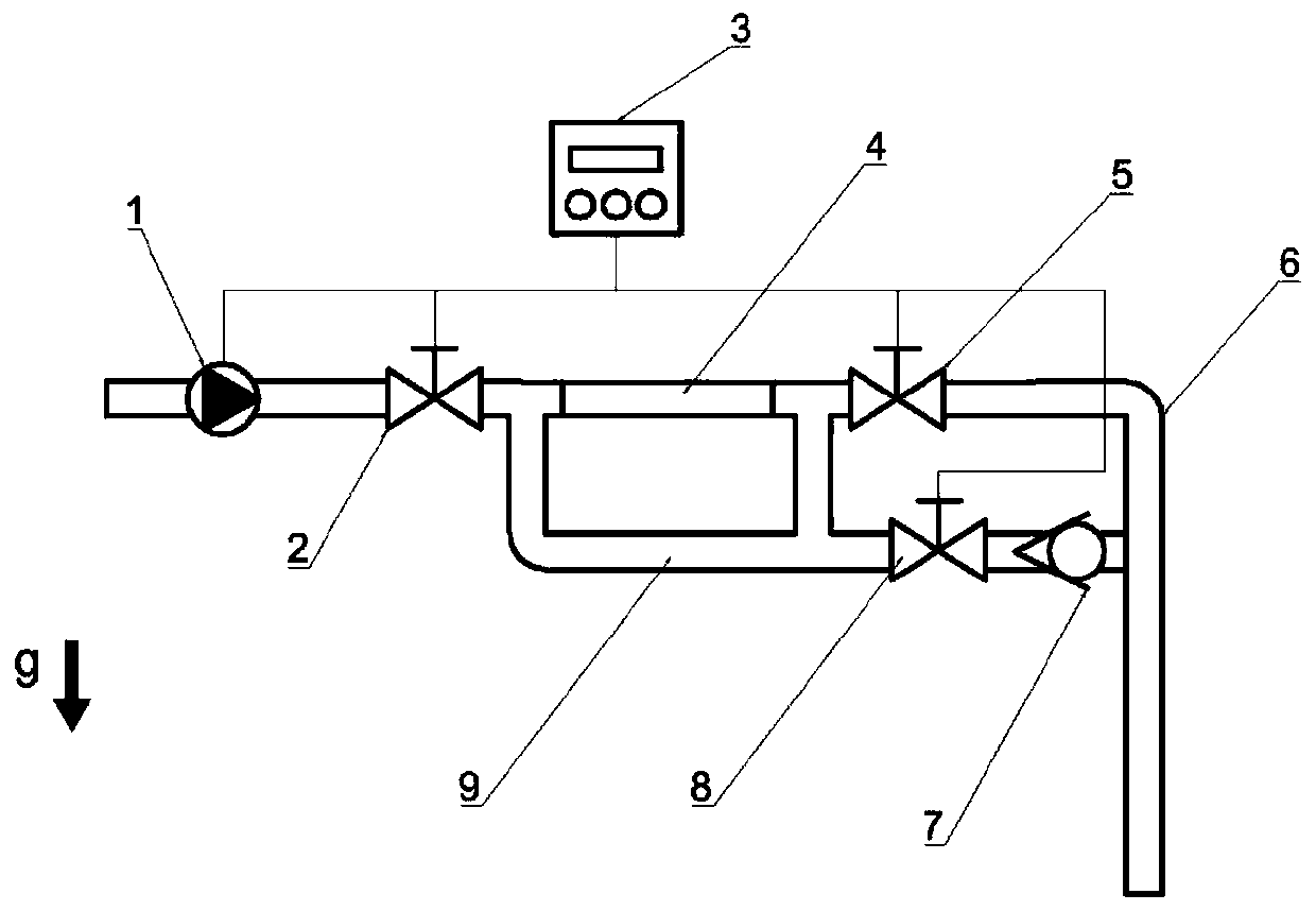
[0029] This embodiment is a small micro-bubble generating device. It is mainly composed of a water pump, a valve, a controller, a bubble generating chamber, a first pipeline, a second pipeline and a one-way valve. The role of the controller is to control the switch of the water pump and drive the servo motor to change the state of the bubble generating chamber.

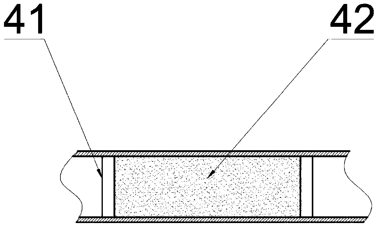
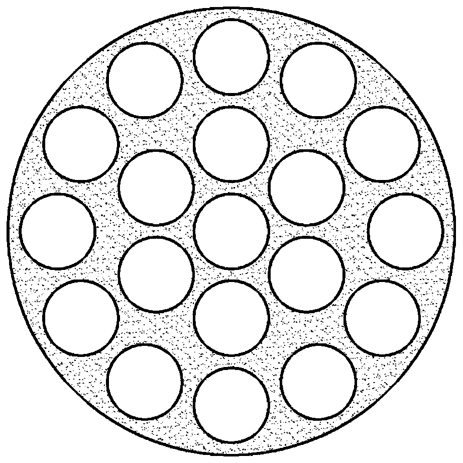
[0030] refer to figure 1 , figure 2 , image 3 . The water pump 1 is installed at the front end of the first pipeline 6 , and the bubble generating chamber 4 is installed at the middle section of the first pipeline 6 . There is a filter box 41 in the bubble generation chamber 4, and the solid reaction raw material block 42 is housed in the filter box 41. The solid reaction raw material block 42 is mainly formed by press...


PUM


Abstract

The invention discloses a small micro-bubble generator and a method, and belongs to the field of micro-bubble drag reduction. The generator comprises a water pump, three valves, a controller, a bubblegeneration chamber, a first pipeline, a second pipeline and a one-way valve. The water pump, a first valve, the bubble generation chamber and a second valve are sequentially mounted on the first pipeline; a solid reaction raw material block is mounted in the first pipeline through a filter screen box to form the bubble generation chamber; a first port and a second port of a second pipeline are connected with two ends of the bubble generation chamber and are positioned between the first valve and the second valve; and a third port of the second pipeline is connected with the outlet end of thefirst pipeline, and a third valve and the one-way valve are installed between the second port and the third port. According to the device, a carbon dioxide gas is generated through reaction of mixed solids of water, an organic acid and sodium bicarbonate, generated bubbles are small, density is large, drag reduction is better facilitated, distribution in water flow is uniform, an extra gas sourcedoes not need to be carried, and the device is small in size and low in cost.

Description

technical field [0001] The invention belongs to the field of micro-bubble drag reduction, and in particular relates to a small micro-bubble generator and a method. Background technique [0002] The resistance of ships and underwater vehicles is dominated by viscous resistance, wave-making resistance accounts for a small part, and frictional resistance accounts for the vast majority of viscous resistance. Therefore, how to reduce this type of frictional resistance has attracted the attention of many researchers. Micro-bubble drag reduction technology is to use the difference in density and viscosity between the gas medium and the liquid medium to continuously spray tiny bubbles near the boundary layer of the wall to form a gas-liquid two-phase mixed flow to isolate part of the fluid from the wall. , to replace the solid-liquid interface with the gas-liquid interface, so as to achieve the effect of reducing frictional resistance. Scholar Tokunaga achieved an exciting result o...

Claims


Application Information

Patent Timeline
Patent Type & Authority Applications(China)
IPC IPC(8): B63B1/38B63B1/40
CPCB63B1/38B63B1/40B63B2001/387Y02T70/10
Inventor 胡海豹史瑞琦郑美云冯家兴孟凡哲杜鹏黄潇陈效鹏
Owner NORTHWESTERN POLYTECHNICAL UNIV
Why Eureka
Try Eureka