A multi-component thermal fluid generation system for petroleum thermal recovery using petroleum coke as fuel

A technology of multi-component thermal fluid and generation system, which is applied in the fields of exploiting fluid, burning with multiple fuels, burning with lump fuel and powder fuel, etc., can solve the problems such as the structural setting of the burner is not given, and the burning efficiency needs to be verified. , to achieve the effect of improving atomization effect, stable combustion, and ensuring stable combustion

Active Publication Date: 2020-12-22
江苏亦通石油科技有限公司
View PDF9 Cites 0 Cited by
  • Summary
  • Abstract
  • Description
  • Claims
  • Application Information

AI Technical Summary

Problems solved by technology

However, this patent application does not provide a specific burner structure setting, and the actual combustion efficiency remains to be verified
From the perspective of practical application, there is no practical application of heavy oil thermal recovery technology using petroleum coke as fuel at present, which also confirms from the side that petroleum coke is used instead of natural and diesel oil as the fuel of multi-element thermal fluid generator. Technical difficulty, the stability of the water coke slurry burner to fully atomize and burn the water coke slurry is also the difficulty of restricting the application of petroleum coke as a fuel in the multi-component thermal fluid generator

Method used


Image

  • A multi-component thermal fluid generation system for petroleum thermal recovery using petroleum coke as fuel
  • A multi-component thermal fluid generation system for petroleum thermal recovery using petroleum coke as fuel
  • A multi-component thermal fluid generation system for petroleum thermal recovery using petroleum coke as fuel

Examples


Embodiment

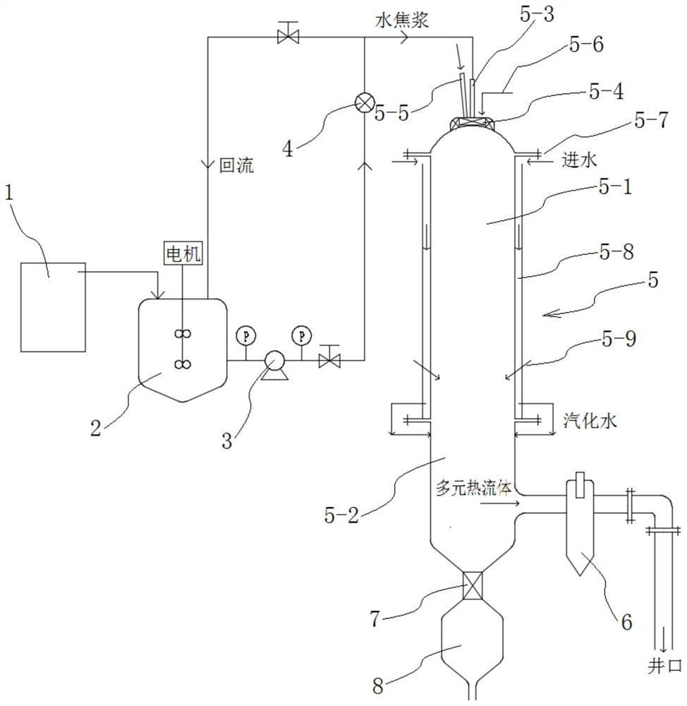
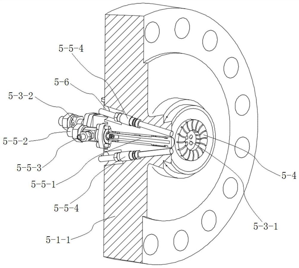
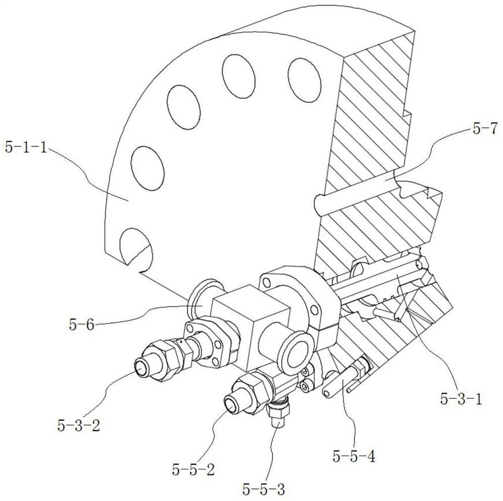
[0052] like Figure 1 to Figure 7As shown, a multi-component thermal fluid generating system for petroleum thermal recovery using petroleum coke as fuel in this embodiment includes a pulping device 1, a stirring tank 2, a high-pressure pump 3, a burner 5, a high-temperature separator 6 and a slag storage tank 8. Pulping device 1 is used to make petroleum coke into water coke slurry. Existing petroleum coke pulping equipment can be used. Water coke slurry is usually composed of petroleum coke powder, water and additives. In order to improve the combustion of water coke slurry Performance, in the present embodiment, the mass percentage component of the water coke slurry prepared by pulping device 1 is: petroleum coke (powder): 75%; Water: 22%; Fixing agent: 3%; The water coke slurry after configuration The fixed viscosity concentration reaches 80wt%, which improves the stability of the coke slurry, makes the coke slurry have good slurrying properties, facilitates the atomization...


PUM


Abstract

The invention discloses a petroleum heat extraction multiple thermal fluid generation system adopting petroleum coke as fuel, and belongs to the technical field of petroleum heat extraction. The petroleum heat extraction multiple thermal fluid generation system comprises a slurrying device, a stirring tank, a high-pressure pump, a combustor, a high-temperature separator and a slag storage tank, and the combustor is overall vertically arranged, comprises a combusting chamber and a vaporizing chamber formed in the lower part of the combusting chamber, and further comprises an atomization spray gun, a cyclone and an auxiliary ignition device which are arranged at the top of the combusting chamber. The top swirling combustor cooperates with the auxiliary ignition device, thus water-coke slurryand a combustion improver are mixed and then subjected to high-pressure swirling spray combustion, it is ensured that the water-coke slurry and the combustion improver are sufficiently mixed and atomized, swirl combustion is formed by the cyclone to enhance homogeneous charge compression ignition of the water-coke slurry, the homogeneous charge compression ignition time is prolonged, sufficient combustion of the water-coke slurry is ensured, coke embers and the carbon content of fly ash are reduced, thus the petroleum coke becomes possible for serving as the fuel of a multiple thermal fluid generator, and the cost of multiple thermal fluid thickened oil miming is lowered.

Description

technical field [0001] The invention relates to a multi-component thermal fluid generation system for petroleum thermal recovery, more specifically, a multi-component thermal fluid generation system for petroleum thermal recovery with petroleum coke as fuel. Background technique [0002] Heavy oil production in oilfields is mainly based on steam huff and puff and steam flooding, but there are problems such as small heat sweep range, poor recovery effect, and large heat loss. Therefore, in the later stage of huff and puff development, gas-assisted steam injection such as nitrogen / carbon dioxide is generally used to improve the thermal recovery effect, which is the feature and advantage of the multi-component thermal fluid oil recovery technology. Multi-component thermal fluid thermal recovery technology is a comprehensive oil recovery method that efficiently utilizes the synergistic effects of nitrogen, carbon dioxide, water vapor and combustion heat. Through heating and gas ...

Claims


Application Information

Patent Timeline
Patent Type & Authority Patents(China)
IPC IPC(8): F23C1/00F23C5/08F23K1/02F23L7/00E21B43/24
CPCE21B43/24F23C1/00F23C5/08F23K1/02F23L7/007Y02E20/34
Inventor 梅奕中徐梁殷坚张孜义张建忠赵爽
Owner 江苏亦通石油科技有限公司
Why Eureka
Try Eureka