Optical lens wavefront measurement method using phase measurement deflection technology

An optical lens and phase measurement technology, applied in the field of optical imaging, can solve the problems of low resolution and high cost, achieve high sensitivity, low cost, and improve the signal-to-noise ratio.

Inactive Publication Date: 2020-08-14
UNIV OF ELECTRONICS SCI & TECH OF CHINA
View PDF4 Cites 6 Cited by
  • Summary
  • Abstract
  • Description
  • Claims
  • Application Information

AI Technical Summary

Problems solved by technology

Shack-Hartmann wavefront sensor (SHWFS) is a conventional pupil surface wavefront sensor, which is characterized by high precision, low environmental requirements, fast processing speed, and dynamic and real-time detection of wavefront. It is a very commonly used wavefront detection However, the number of sampling points of this method is limited by the number of sub-eyes of the microlens array, the resolution is low, and the cost is high

Method used


Image

  • Optical lens wavefront measurement method using phase measurement deflection technology
  • Optical lens wavefront measurement method using phase measurement deflection technology
  • Optical lens wavefront measurement method using phase measurement deflection technology

Examples


Embodiment 1

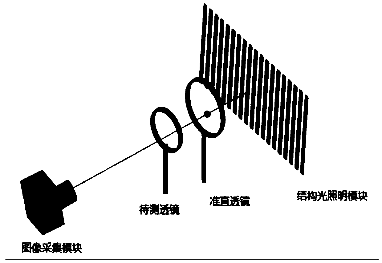
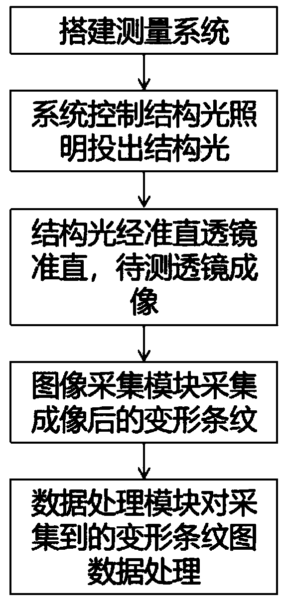
[0035] Such as Figure 1-2 As shown, the present invention provides a method for measuring the wavefront of an optical lens using phase measurement deflection, which includes the following steps:

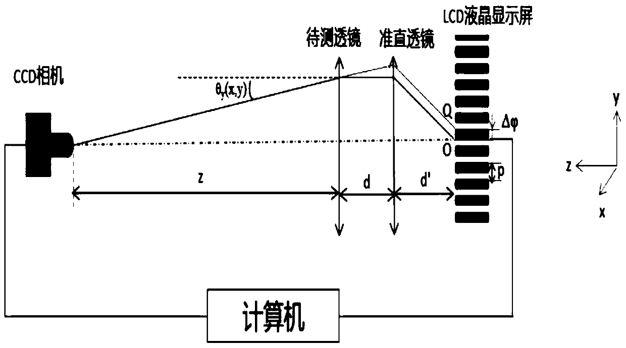
[0036] Step 1. Use a computer to generate a phase-shifted sinusoidal fringe structured light as a light source. The structured light is collimated and projected onto the surface of the lens to be tested, and imaged by it. The lens to be tested can be a single lens or a combination. For lenses or other phase objects, structured light passes through the lens to be tested, refracts inside it, and exits at a certain deflection angle, thereby forming deformed fringe structured light;

[0037] Step 2: The image acquisition module collects the deformed fringe structured light;

[0038] Step 3. Use the phase shift recovery algorithm to extract the wrapped phase in the structured light by using the collected light intensity of the deformed fringe structured light; use the phase unwrapping algorith...


PUM


Abstract

The invention relates to an optical lens wavefront measurement method using a phase measurement deflection technology. The method comprises the steps of building a phase measurement deflection technology transmission system, sequentially arranging a CCD camera, a collimating lens, a to-be-measured optical lens, an LCD display screen and an acquisition control computer on a light path, introducingthe collimating lens to collimate stripe light, and reducing structured light distortion caused by light divergence. Due to the fact that the to-be-measured lens has a phase modulation effect, stripesare imaged to form deformed stripes, the wrapping phase of the stripes is calculated by using a four-step phase shift algorithm or Fourier transform, the gradient is derived and extracted by using alight inverse tracing method, and the wavefront slope is integrated by using a regional wavefront reconstruction algorithm to obtain characteristics of the wavefront distribution. The method providedby the invention is simple in structure, is suitable for the wavefront detection of various types of phase objects, not only can obtain the phase distribution of the phase objects, but also can obtainthe wavefront distribution, and has the characteristics of rapidness and easy operation.

Description

Technical field [0001] The invention belongs to the technical field of optical imaging, and particularly relates to a method for measuring the wavefront of an optical lens using phase measurement deflection technique. Background technique [0002] As we all know, with the development of science and technology, the requirements for measurement accuracy and resolution of optical components are getting higher and higher. The optical lens manufacturing process includes optical design, precision machining, measurement and other links, which require high accuracy and measurement speed. At present, there are many methods for measuring the wavefront of optical components. Interferometry is often used to measure the wavefront. Shearing interferometers use the measured wavefront and its own wave after some transformation (lateral or radial shear, etc.) In order to complete the interferometric measurement through the previous comparison, coherent illumination and a set of precisely designe...

Claims


Application Information

Patent Timeline
Patent Type & Authority Applications(China)
IPC IPC(8): G01M11/02G01J9/00
CPCG01J9/00G01J2009/002G01M11/02
Inventor 王维岳慧敏覃添刘永
Owner UNIV OF ELECTRONICS SCI & TECH OF CHINA
Why Eureka
Try Eureka