Mid-infrared band ultra-short pulse spectrum detection device

An infrared band, ultra-short pulse technology, applied in the optical field, can solve the problems of infeasibility, difficult high-order dispersion, easy darkening, etc., to achieve the effect of real-time measurement and low loss

Active Publication Date: 2020-08-25
XUZHOU NORMAL UNIVERSITY
View PDF3 Cites 2 Cited by
  • Summary
  • Abstract
  • Description
  • Claims
  • Application Information

AI Technical Summary

Problems solved by technology

The inherent poor mechanical strength of ZBLAN optical fiber, easy darkening, low melting point makes it difficult to realize full optical fiber, and it is in deep negative dispersion, it is difficult to accurately compensate for high-order dispersion, and it is not easy to obtain pulses of the order of few cycles
And the price is expensive, there is no feasibility, it is difficult to realize commercial promotion, industrialization and application
[0010] At present, there is an urgent demand for mid-infrared band lasers in both military and civilian fields. Therefore, carrying out real-time detection research in this band has important application value for the research of laser materials and laser technology in the mid-infrared band and real-time spectral monitoring.

Method used


Image

  • Mid-infrared band ultra-short pulse spectrum detection device
  • Mid-infrared band ultra-short pulse spectrum detection device
  • Mid-infrared band ultra-short pulse spectrum detection device

Examples


example 1

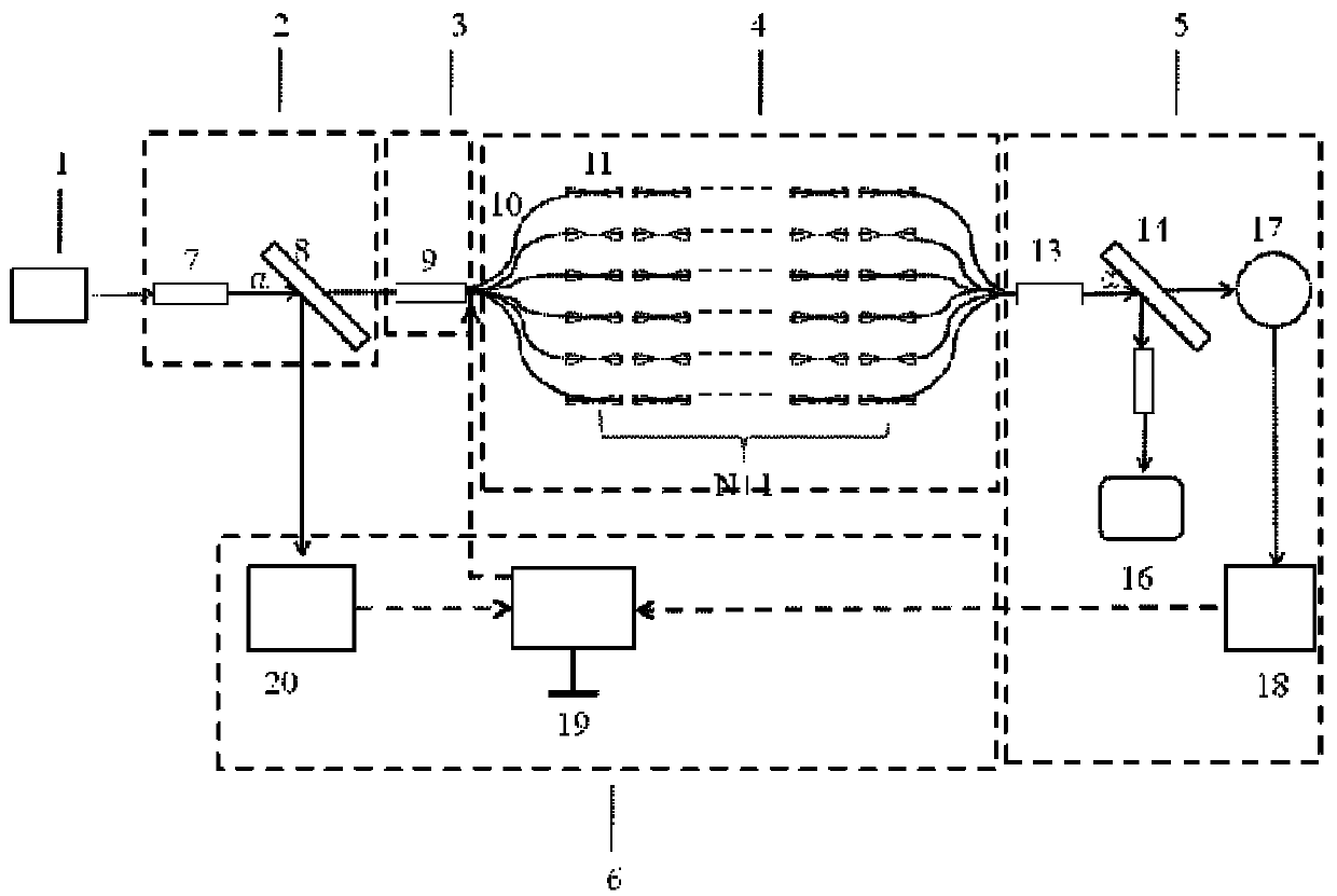
[0104] The above-mentioned mid-infrared band ultrashort pulse spectrum detection device includes an optical signal receiving module, a signal strength adaptive module, a dispersion management module, a signal detection module, and a control feedback module. The optical signal receiving device includes an input collimator and a beam splitter I. The input collimator and the beam splitter I are fixed in the collimated optical path to ensure that the input light can be coupled into the system through the input collimator, and the beam splitter I is placed at 45° to ensure that about 10% of the light can be measured by the real-time oscilloscope II , and the rest of the incident light is transmitted to the dispersion management module along the optical path. The signal strength adaptive module includes an attenuator I, and the attenuator I is placed in front of the dispersion management module to adjust the intensity of the signal light.

[0105] The dispersion management module i...

example 2

[0112] The difference between this example and Example 1 is that this example uses a negatively chirped pulse as the input signal, and GDD describes a nonlinear phase shift, that is, the linear relationship between the frequency component of the pulse and the group velocity delay. If the second derivative of the medium's refractive index with respect to wavelength. It indicates that the medium is a positive dispersion medium, and the pulse will produce normal dispersion during the transmission process through the medium, that is, the transmission speed of the high frequency component of the incident pulse is slower than that of the low frequency component, and the front edge of the pulse will be red-shifted during the pulse transmission process, and the trailing edge of the pulse will be Blue shift occurs, this phenomenon is called positive chirp; if the second derivative of the medium's refractive index to wavelength indicates that the medium is a negative dispersion medium, a...

example 3

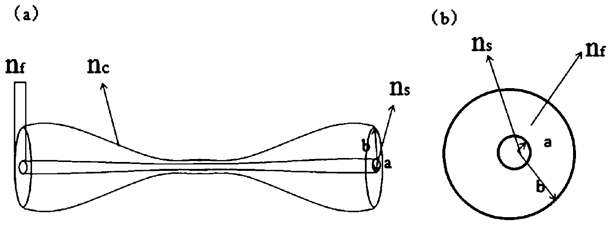
[0115] see Figure 9 and Figure 10 , Figure 9 Among them, a represents the time domain diagram of the input signal light source, b represents the spectrum diagram of the input signal light source; c represents the time domain diagram of the input signal light source through optical time stretching; d represents the time domain diagram of the input signal light source through optical time stretching. The air-core fused silica micro-nano fiber proposed in this example makes it possible to apply DFT in the mid-infrared band, especially solving the problem of real-time detection of ultrafast laser sources in the band above 2.4 microns transmitted by non-silica-based fibers. The difference between this example and Example 1 is that this example uses a laser pulse with a wavelength of 2860nm as the input signal. The length of a micro-nano fiber used in the experiment is 40mm, and the total GVD after connecting 50 fibers in series is 50ps 2 / km. The sampling rate of the real-tim...


PUM

PropertyMeasurementUnit
radiusaaaaaaaaaa
thicknessaaaaaaaaaa
radiusaaaaaaaaaa

Abstract

The invention discloses a mid-infrared band ultra-short pulse spectrum detection device, which is characterized in that an optical signal receiving module, a signal intensity adaptive module, a dispersion management module and a signal detection module are arranged on the same collimation optical path in sequence and form a feedback loop with a control feedback module; input light generated by aninput signal light source passes through the optical signal receiving module. The input light is coupled into a dispersion management module through an input collimator, and one path of output light is split from the input light through a beam splitter I to be coupled into a control feedback module; independent control of dispersion intensity and non-linear intensity can be realized, wherein the dispersion management module is used to realize linear conversion from an optical signal frequency domain to a time domain by utilizing a dispersion Fourier transform technology guided by large group velocity dispersion and low nonlinear characteristics of micro-nano optical fibers; finally, measurement of ultrashort pulse sub-picosecond magnitude transient characteristics can be realized, and timedomain and frequency domain information can be accurately obtained.

Description

technical field [0001] The invention relates to the field of optical technology, in particular to a mid-infrared band ultrashort pulse spectrum detection device. Background technique [0002] The interaction between femtosecond pulsed laser and medium, due to its large energy, high peak power and high beam quality, it has unique characteristics such as small action area, small thermal effect, and spatial selectivity that are different from long-pulse lasers, making femtosecond fiber lasers already available. Widely used in ultra-fine processing, micro-photonic device manufacturing, medical precision surgery, nano-biological engineering and other aspects. The generation of femtosecond pulsed laser mainly comes from mode-locking technology. The application of active mode-locking technology, passive mode-locking, additive pulse mode-locking and other technologies can compress the laser pulse to the level of picosecond or even femtosecond. [0003] Due to the special waveguide ...

Claims


Application Information

Patent Timeline
Patent Type & Authority Applications(China)
IPC IPC(8): G01J3/28G01J3/02G01J11/00
CPCG01J3/28G01J3/0218G01J11/00G01J2003/283
Inventor 周伟曹雪王敬如鲜安华王昊天沈德元唐定远陈祥朱强邓磊李雷李仙尼李亦非丁瑾蓉
Owner XUZHOU NORMAL UNIVERSITY
Why Eureka
Try Eureka