
SCR denitration coal-fired power plant liquid slagging boiler waste gas treatment system and method

A technology of liquid slag discharge and boiler exhaust gas, which is applied in the direction of chemical instruments and methods, separation methods, gas treatment, etc., can solve the problems of hindering the downstream flow of slag liquid, polluting the production site, and fluctuating slag hopper airflow, so as to avoid clogging of slag liquid, The effect of preventing safety accidents

Pending Publication Date: 2020-09-01
天津华能杨柳青热电有限责任公司 +2
View PDF0 Cites 0 Cited by
  • Summary
  • Abstract
  • Description
  • Claims
  • Application Information

AI Technical Summary

Problems solved by technology

However, due to the liquid slag discharge characteristics of the liquid slag discharge boiler, when the high-temperature slag liquid enters the slag pool, the high-temperature slag liquid is rapidly cooled by water to generate a large amount of water vapor, and the air flow in the slag hopper fluctuates greatly, which easily forms a positive pressure in the slag hopper , prevent the slag liquid from flowing down, reduce the temperature of the slag chamber, and cause the slag liquid to be blocked. At the same time, the waste gas and smoke in the slag hopper will rush out of the fire hole with the positive pressure, polluting the production site, and accompanied by the high-temperature slag liquid entering the slag hopper. Some high-temperature flue gas contains a large amount of dust and sulfur dioxide air pollutants. These pollutants will also rush out of the slag hopper to pollute the production site with the positive pressure of the slag hopper
These conditions have seriously affected the safe operation of the boiler, which has become an urgent problem to be solved for large coal-fired power plant liquid slagging boilers

Method used


Image

  • SCR denitration coal-fired power plant liquid slagging boiler waste gas treatment system and method
  • SCR denitration coal-fired power plant liquid slagging boiler waste gas treatment system and method

Examples


Embodiment Construction

[0022] The following will clearly and completely describe the technical solutions in the embodiments of the present invention with reference to the accompanying drawings in the embodiments of the present invention. Obviously, the described embodiments are only some, not all, embodiments of the present invention.

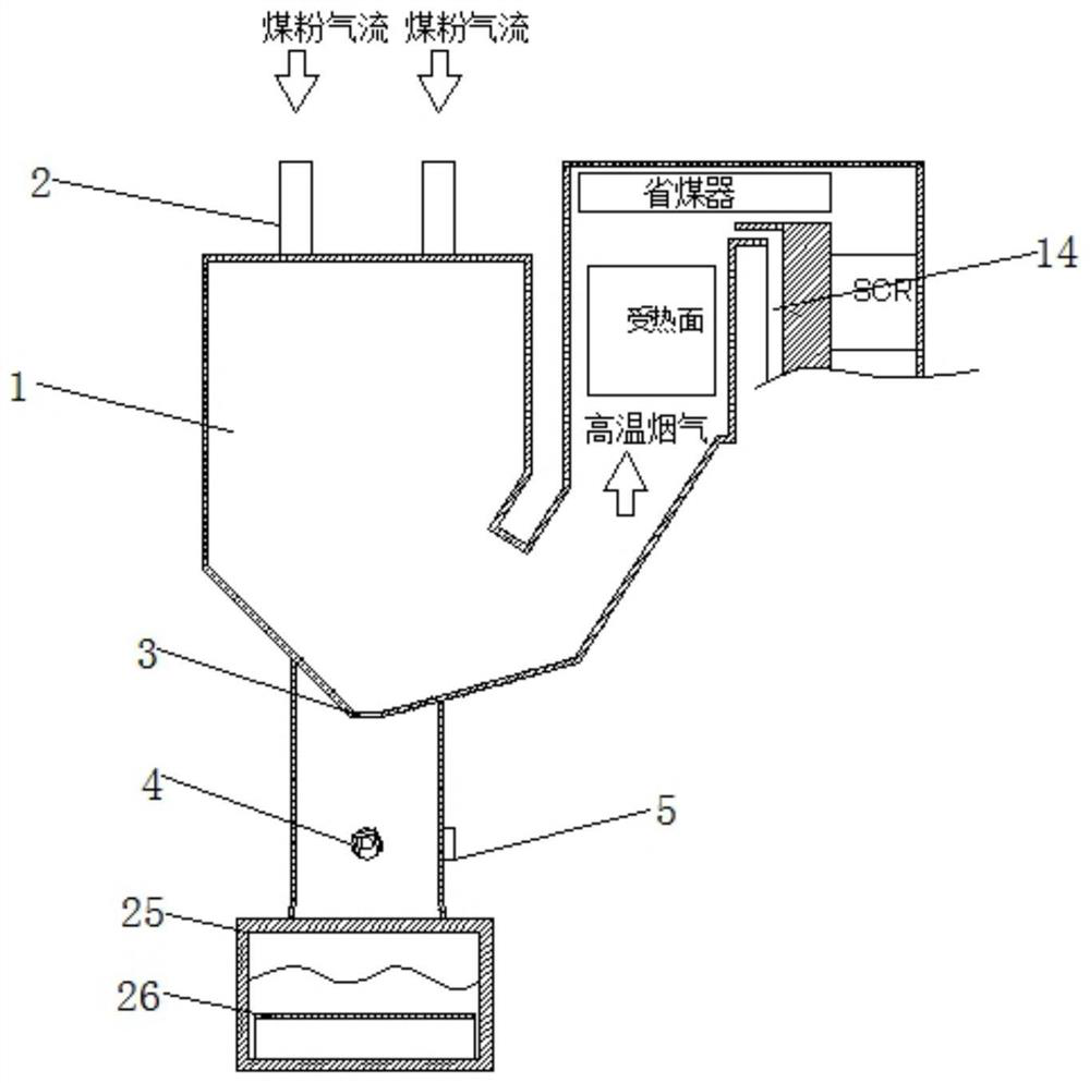
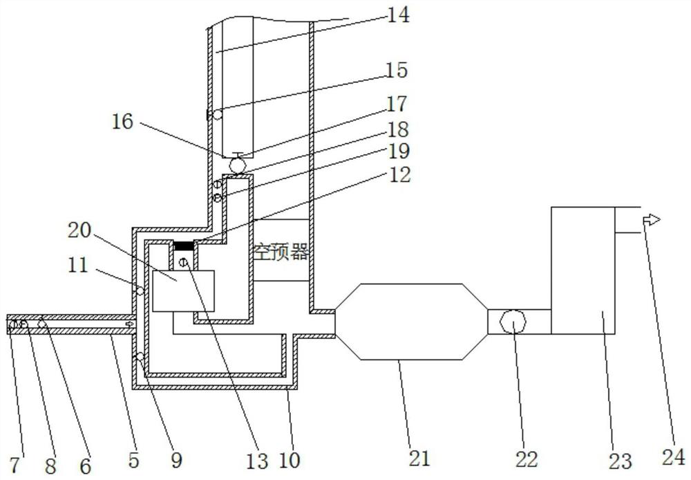
[0023] refer to Figure 1-2 , an SCR denitrification coal-fired power plant liquid slagging boiler waste gas treatment system, including a boiler slag system, a waste flue gas pollutant purification system, a waste gas SCR denitrification system, and a waste slag treatment system. The waste slag treatment system includes a slag pool 25 and a slag removal machine 26. The waste gas pollutant purification system includes the waste gas pipe interface 4, the waste gas pipe 5, the waste gas pipe regulating door 6, the waste gas temperature measuring point 7 and the waste gas flow measuring point 8, the waste gas pipe connection 4 is connected with the waste gas pipe 5, and ...


PUM


Abstract

The invention discloses an SCR denitration coal-fired power plant liquid slagging boiler waste gas treatment system. The system comprises a boiler slag system, a waste flue gas pollutant purificationsystem, a waste gas SCR denitration system and a waste residue treatment system. The waste residue treatment system comprises a residue pool and a residue fishing machine. The waste flue gas pollutantpurification system comprises a waste gas pipe connector, a waste gas pipeline, a waste gas pipe adjusting door, a waste gas temperature measuring point and a waste gas flow measuring point. The waste gas pipe connector is connected with the waste gas pipeline. The waste gas pipe adjusting door, the waste gas temperature measuring point and the waste gas flow measuring point are all arranged on the inner wall of the waste gas pipeline. The waste gas SCR denitration system comprises a dust remover. The newly added waste gas SCR denitration system and the dust remover, an induced draft fan anddesulfurization tower equipment of a large coal-fired power plant unit are used for extracting and removing waste flue gas pollutants generated in a slag hopper of a liquid slagging boiler, and environment-friendly detection equipment of the large coal-fired power plant unit is used for real-time monitoring.

Description

technical field [0001] The invention relates to the technical field of liquid slagging boiler waste gas treatment, in particular to a liquid slagging boiler waste gas treatment system and method for SCR denitrification coal-fired power plants. Background technique [0002] Large-scale coal-fired power plant liquid slag boilers use high furnace temperature to melt ash into a fluid form, and the slag liquid falls into the slag pool through the slag outlet at the bottom of the furnace, so as to achieve the purpose of reducing the volume of ash and slag. However, due to the liquid slag discharge characteristics of the liquid slag discharge boiler, when the high-temperature slag liquid enters the slag pool, the high-temperature slag liquid cools rapidly with water to generate a large amount of water vapor, and the air flow in the slag hopper fluctuates greatly, which easily forms a positive pressure in the slag hopper , prevent the slag liquid from flowing down, reduce the temper...

Claims


Application Information

Patent Timeline
IPC IPC(8): B01D53/86B01D53/56B01D53/48F23J1/08
CPCB01D53/8625B01D53/48F23J1/08B01D2258/0283
Inventor 周昊马翔张海东刘涛刘强孙会亮陈香保张鹤房凡王瑞超王明磊郭守莹李若灿王辉高沛
Owner 天津华能杨柳青热电有限责任公司
Learn More