A gypsum powder air separator

An air flow separator and air flow separation technology, which are applied in the separation of solids from solids by air flow, solid separation, chemical instruments and methods, etc., can solve the problems affecting product quality and work efficiency, gypsum powder quality decline, and labor intensity. and other problems, to achieve the effect of good promotion and use value, prolonged drying time and low production cost

Active Publication Date: 2022-07-12
山东腾飞机电科技有限公司
View PDF0 Cites 0 Cited by
  • Summary
  • Abstract
  • Description
  • Claims
  • Application Information

AI Technical Summary

Problems solved by technology

[0003] Industrial by-product gypsum contains a certain amount of impurities such as cinders, stones, and large-grained anhydrite; industrial by-product gypsum is removed by hammer dryers and airflow dryers to remove surface water and a small amount of crystal water, and then separated by rotary sieves. The granulated impurities enter the fluidized furnace for calcination. In the process, the rotary sieve plays the role of separating the granulated impurities. The screen size of the rotary sieve is 3mm*3mm. If it is less than 3mm, it will enter the calciner. The gypsum powder working process in the calciner is high-level feed and high-level output. Particles larger than 1mm cannot go out. With long-term accumulation, a large amount of large-scale particles will accumulate in the bottom of the fluidized furnace, resulting in poor boiling and a decline in the quality of gypsum powder. We can only stop the machine to clean the large particles of impurities in the bottom of the fluidized furnace.
The more particles in the raw paste, the more frequent the furnace cleaning. Generally, the furnace needs to be cleaned once every 10-15 days. The cleaning time takes about 4 hours. The labor intensity is high, which seriously affects the product quality and work efficiency.

Method used


Image

  • A gypsum powder air separator
  • A gypsum powder air separator
  • A gypsum powder air separator

Examples


Embodiment

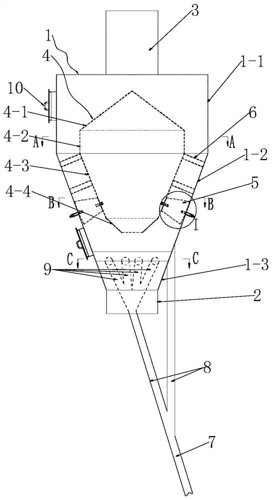
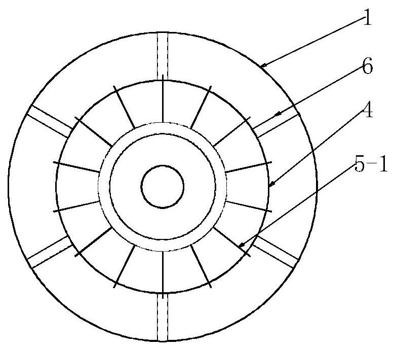
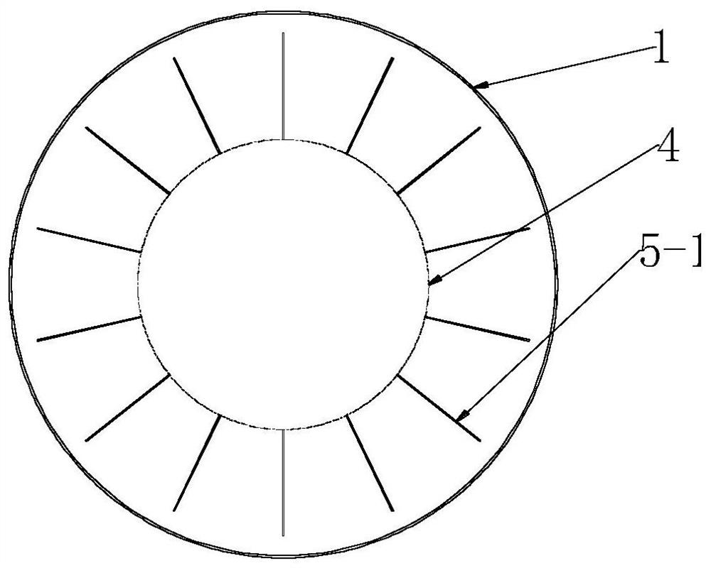
[0034] as attached figure 1 As shown, the structure of the gypsum powder airflow separator of the present invention mainly includes an airflow separation cylinder 1, a material blocking cylinder 4, a wind blocking structure 5 and a large particle outflow structure. The air separation cylinder 1 is a cylinder structure composed of a cylindrical deceleration part 1-1, a conical blocking part 1-2 and a conical buffer part 1-3 arranged in sequence from top to bottom; the upper end of the cylindrical deceleration part 1-1 is installed with a The inner diameter of the barrel 3, the discharge barrel 3 is smaller than the inner diameter of the cylindrical deceleration part 1-1; the inner diameter of the cylindrical deceleration part 1-1 is not less than the maximum inner diameter of the cone stopper 1-2, and the cone stopper is wider than 1-2. The structure with a narrow lower part is arranged at the lower end of the cylindrical deceleration part 1-1 and the minimum inner diameter of ...


PUM


Abstract

The invention discloses a gypsum powder airflow separator, which belongs to the gypsum powder production equipment. The technical problem to be solved by the invention is how to avoid the accumulation of large particles at the bottom of the boiling furnace, ensure the boiling effect, improve the quality of the gypsum powder, and at the same time reduce the times of cleaning the furnace, To reduce the labor intensity of workers and improve the work efficiency, the technical scheme adopted is as follows: the structure includes an airflow separation cylinder, a feed cylinder is arranged at the lower end of the airflow separation cylinder, a discharge cylinder is arranged at the upper end of the airflow separation cylinder, and an upper middle part of the airflow separation cylinder is arranged. The position is provided with a material blocking cylinder, a wind blocking structure is set between the outer side wall of the material blocking cylinder and the inner side wall of the airflow separation cylinder, and a large particle outflow structure is set at the lower position of the middle part of the airflow separation cylinder, and the inlet end of the large particle outflow structure is located in the airflow. At the lower position in the middle of the separation cylinder, the outlet end of the large particle outflow structure is located at the obliquely lower position outside the air separation cylinder.

Description

technical field [0001] The invention relates to gypsum powder production equipment, in particular to a gypsum powder airflow separator. Background technique [0002] Industrial by-product gypsum refers to the by-product or waste residue with calcium sulfate as the main component generated by chemical reaction in industrial production, mainly including phosphogypsum, desulfurized gypsum, citric acid gypsum, fluorine gypsum, salt gypsum, monosodium glutamate gypsum, copper gypsum and titanium gypsum Gypsum etc. The industrial by-product gypsum usually cannot be directly utilized due to its large free water content and many harmful impurities. Dehydration of industrial by-product gypsum to convert gypsum dihydrate into β-CaSO 4 ·0.5H 2 O phase, can prepare plaster of Paris and products. [0003] The industrial by-product gypsum contains a certain amount of impurities such as cinders, stones, large particles of anhydrite, etc. The industrial by-product gypsum is removed by a...

Claims


Application Information

Patent Timeline
Patent Type & Authority Patents(China)
IPC IPC(8): B07B7/01B07B7/04B07B11/02C01F11/46C04B11/02C04B11/26
CPCB07B7/01B07B7/04B07B11/02C04B11/02C04B11/26C01F11/466C01F11/468
Inventor 李传臣聂秀常张宝松张德生王臣姚永斌杨同
Owner 山东腾飞机电科技有限公司
Why Eureka
Try Eureka