Wireless power transmission magnetic coupling system structure parameter optimization method based on SSP compensation

A technology of wireless power transmission and optimization method, applied in the direction of constraint-based CAD, design optimization/simulation, CAD numerical modeling, etc., can solve the influence of the coil output efficiency and the influence of the wireless power transmission efficiency are not considered. , limit the optimal design scheme of magnetic coupling structure, etc.

Active Publication Date: 2020-09-04
FUZHOU UNIV
View PDF4 Cites 8 Cited by
  • Summary
  • Abstract
  • Description
  • Claims
  • Application Information

AI Technical Summary

Problems solved by technology

This largely limits the optimal design of the magnetic coupling structure, and does not take into account the influence of the internal impedance of the coil on the output efficiency of the coil.
Although the resonant parallel capacitance adopted by the wireless power transmission S / SP compensation topology reduces the reactive component of the primary current and realizes the system to be purely resistive, it does not take into account its influence on the efficiency of wireless power transmission

Method used


Image

  • Wireless power transmission magnetic coupling system structure parameter optimization method based on SSP compensation
  • Wireless power transmission magnetic coupling system structure parameter optimization method based on SSP compensation
  • Wireless power transmission magnetic coupling system structure parameter optimization method based on SSP compensation

Examples


Embodiment 1

[0134] Embodiment 1: The input and output indicators are DC input U in =400V, the maximum outer diameter of the transmitting coil R pmaxout =0.15m, the maximum outer diameter R of the receiving outer diameter coil smaxout =0.15m, transmission distance d=0.1m, working frequency f=100kHz, constant voltage output U o =36V, rated current I o = 5A rated load R o =7.2Ω, output power P o = 180W.

[0135] Step 1: Deduce the input-output relationship and the equivalent transformation ratio of the system according to the main circuit topology.

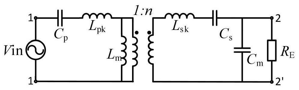
[0136] The main circuit topology of the present invention is as Image 6 shown. The invention adopts a symmetrical half-bridge to obtain high-frequency voltage excitation.

[0137] The switching tube control strategy of the symmetrical half bridge is that the upper and lower tubes are turned on in turn within one cycle, and the duty cycle is 0.5 when the dead zone is not considered.

[0138] u ab is the high-frequency square wave volta...


PUM


Abstract

The invention relates to a wireless power transmission magnetic coupling system structure parameter optimization method based on SSP compensation. The method includes: establishing an electromagneticfield calculation model of the single-turn planar spiral coil; obtaining the coupling coefficient of the single-turn planar spiral coil model and the single-turn average inductance of the transmittingcoil and the receiving coil by taking the maximum coupling coefficient between the transmitting coil and the receiving coil as a target; establishing a multi-turn coil magnetic coupling system simulation model to obtain a coupling coefficient and single-turn average inductance of the transmitting coil and the receiving coil at the moment, and comparing the coupling coefficient and the single-turnaverage inductance with a result obtained by the single-turn planar spiral coil model until difference values are smaller than a preset value; and finally, according to the number of turns of the transmitting and receiving coils and the parallel compensation capacitance value, obtaining transformer leakage inductance model resistance and inductance and compensation network parameters of the magnetic coupling system, and configuring circuit parameters. The method enables the system to obtain the minimum winding loss on the premise of guaranteeing the same output index.

Description

technical field [0001] The invention relates to a method for optimizing structural parameters of a wireless power transmission magnetic coupling system based on SSP compensation. Background technique [0002] Resonant wireless energy transmission technology continuously exchanges the magnetic field energy of the inductive coil in the transmitting coil and the electric field energy in the capacitor during resonance, and part of the magnetic field of the transmitting coil is linked to the inductive coil of the receiving coil, and the alternating magnetic field is in the receiving coil. The induced current is induced, and at the receiving end, the electric field energy in the capacitor and the magnetic field energy in the inductor coil continuously transmit energy to the load due to resonance. In order to transmit electric energy efficiently, the resonant frequency of the transmitting coil and the receiving coil is set to the same frequency, which is the resonant frequency of t...

Claims


Application Information

Patent Timeline
Patent Type & Authority Applications(China)
IPC IPC(8): G06F30/23G06F111/04G06F111/10
CPCG06F30/23G06F2111/04G06F2111/10
Inventor 陈庆彬邓小龙陈为
Owner FUZHOU UNIV
Why Eureka
Try Eureka