
Array type plasma device for material surface treatment

A plasma and surface treatment technology, applied in the direction of plasma, electrical components, etc., can solve the problems of difficult processing, large area processing of difficult materials, poor timeliness, etc., to improve stability and timeliness, increase processing area, reduce Effects of processing conditions

Inactive Publication Date: 2020-09-08
XIAN UNIV OF TECH +1
View PDF12 Cites 3 Cited by
  • Summary
  • Abstract
  • Description
  • Claims
  • Application Information

AI Technical Summary

Problems solved by technology

But it also exposed some problems of this technology in the application of material surface treatment, such as poor timeliness of treatment effect (such as "hydrophobic recovery" phenomenon is serious), low plasma uniformity in open gas atmosphere, and irregular shape material surface It is difficult to deal with bottlenecks such as small effective area of ​​jet plasma and uneven array discharge.
[0005] Existing plasma material surface treatment devices, in addition to surface-surface dielectric barrier discharge may produce macroscopically uniform discharge (such as the above-mentioned thin film treatment) in a very small gas gap (generally less than 2mm), most of them cannot avoid discharge The randomness and dispersion of spatial distribution, such as filamentary discharge in air, argon, nitrogen, oxygen and other gas atmospheres, cannot guarantee the uniform treatment effect of materials, and it is difficult to process materials continuously and in large areas

Method used


Image

  • Array type plasma device for material surface treatment
  • Array type plasma device for material surface treatment
  • Array type plasma device for material surface treatment

Examples


Embodiment Construction

[0028] The implementation of the present invention will be described in detail below with examples, so as to fully understand and implement the implementation process of how the present invention uses technical means to solve technical problems and achieve technical effects.

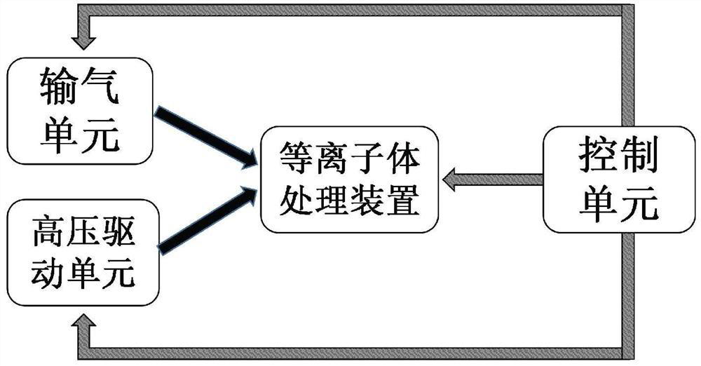
[0029] The embodiment of the present invention discloses an array plasma device for surface treatment of materials, the schematic diagram of which is shown in figure 1 As shown, it includes a plasma processing device, a high-voltage drive unit, a gas delivery unit and a control unit.

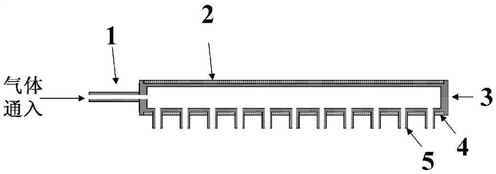
[0030] Such as figure 2 with image 3 As shown, the plasma processing device is equipped with a discharge gas chamber 3, the discharge gas chamber 3 is provided with a gas inlet 1, the upper part of the discharge gas chamber 3 is connected to the high voltage plate electrode 2, and the lower part is connected to the orifice plate electrode 4, and the high voltage plate electrode 3 and the grounded perforated plate elect...


PUM

PropertyMeasurementUnit
diameteraaaaaaaaaa
lengthaaaaaaaaaa
diameteraaaaaaaaaa

Abstract

The invention discloses an array type plasma device for material surface treatment. The array type plasma device comprises a plasma treatment device, a high-voltage driving unit, a gas transmission unit and a control unit, wherein a discharge gas chamber is arranged in the plasma treatment device; a gas inlet is formed in one side of the discharge gas chamber; the upper part of the discharge gas chamber is connected with a high-voltage plate electrode; the lower part of the discharge gas chamber is connected with a grounding perforated plate electrode; a plasma output pipe is arranged at a hole of the grounding perforated plate electrode; the high-voltage plate electrode is connected with the high-voltage driving unit; the gas inlet is connected with the gas transmission unit; and the gastransmission unit, the high-voltage driving unit and the plasma treatment device are respectively connected with the control unit. According to the invention, the uniformity of material surface treatment can be improved, random burn of filamentous discharge to the material surface is avoided, the treatment area is increased, the treatment conditions are reduced, and the stability and timeliness ofthe plasma surface modification effect are improved.

Description

technical field [0001] The invention belongs to the technical field of material surface treatment, and in particular relates to an array plasma device for material surface treatment. Background technique [0002] Surface treatment technology includes surface modification, grafting, polymerization, deposition, etching, etc., which vary according to different application requirements. The advantage is that it does not change the properties of the substrate, but realizes the functionalization of the material surface through directional treatment of the material surface. , such as improving surface hydrophobicity, electrical resistance, barrier, adhesion and printability, etc., has broad application prospects in many fields such as electrical, food, medical and petrochemical industries. [0003] Because low-temperature plasma is rich in active particles such as charge energy and charge, when the surface of the material is modified, it can break the chemical bonds on the surface ...

Claims


Application Information

Patent Timeline
Patent Type & Authority Applications(China)
IPC IPC(8): H05H1/24
CPCH05H1/2406
Inventor 赵妮常正实
Owner XIAN UNIV OF TECH
Learn More