Design method of ultrasonic surface standing wave micro-fluidic chip for micro-particle separation

A microfluidic chip and ultrasonic surface wave technology, applied in the field of microfluidic analysis, can solve the problems of wasting time and cost, and low particle separation efficiency, and achieve the effect of improving separation efficiency

Active Publication Date: 2020-09-15
NANJING UNIV
View PDF6 Cites 6 Cited by
  • Summary
  • Abstract
  • Description
  • Claims
  • Application Information

AI Technical Summary

Problems solved by technology

[0009] In view of the particle separation microfluidic chip existing in the prior art, the parameter design of the ultrasonic surface standing wave action area is only based on empirical judgment, the particle separation efficiency is not high, and a lot of time and cost are wasted. The present invention provides a method for Ultraso

Method used


Image

  • Design method of ultrasonic surface standing wave micro-fluidic chip for micro-particle separation
  • Design method of ultrasonic surface standing wave micro-fluidic chip for micro-particle separation
  • Design method of ultrasonic surface standing wave micro-fluidic chip for micro-particle separation

Examples


Embodiment 1

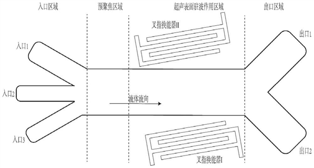
[0048] This embodiment specifically describes an ultrasonic surface standing wave microfluidic chip, which includes a piezoelectric substrate, an interdigital transducer, a microfluidic cavity, and a driving circuit. The interdigital transducer is attached to the piezoelectric substrate, and the interdigital transducer is attached to the piezoelectric substrate. The device emits ultrasonic surface waves, forming a standing field wave on the surface of the substrate, and applies ultrasonic radiation force to the fluid particles in the microfluidic cavity; the microfluidic cavity is bonded or glued to the piezoelectric substrate, and the internal channel section of the microfluidic cavity is rectangular; The driving circuit drives the interdigital transducer to work. The particles enter the microfluidic cavity of the microfluidic chip using the sheath flow technology known in the art. Under the action of the ultrasonic surface standing wave, different types of particles present di...

Embodiment 2

[0071] This embodiment is basically the same as embodiment 1, except that the two particle radii of this embodiment are closer, and the microfluidic chip of this embodiment is a PM-SSAW chip.

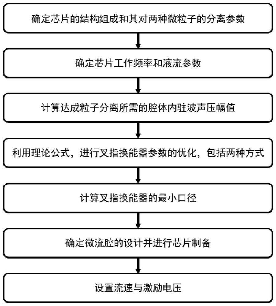
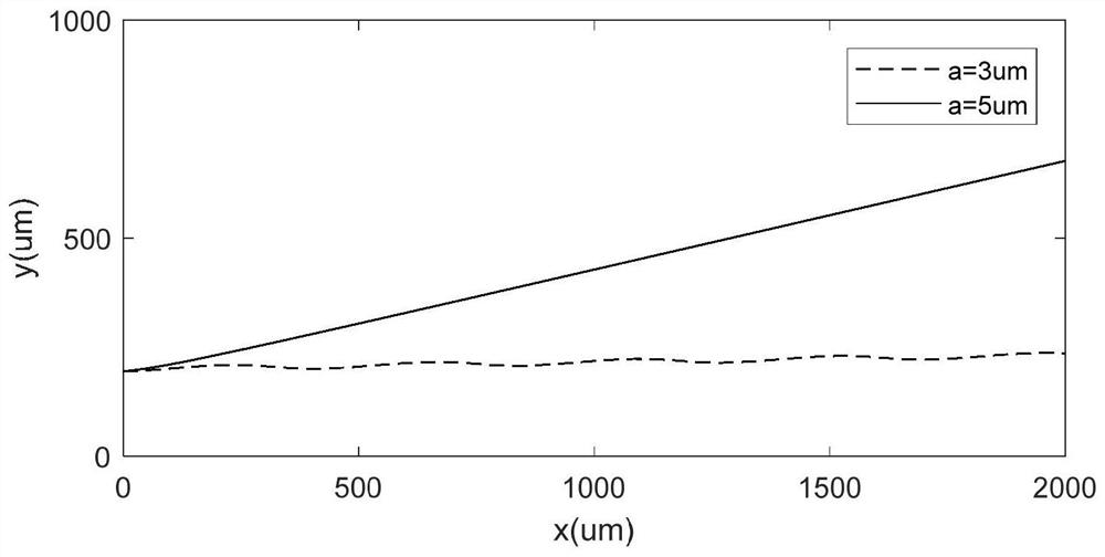
[0072] In this implementation, polystyrene (PS) microspheres with a radius of 3 μm and 3.8 μm are separated. Requires separation purity d> 0.95, particle flux P=100 particles / sec. According to the parameters of the particles to be separated, the cavity size, particle fluid flow rate and ultrasonic action area width of the microfluidic cavity of the chip are calculated. Specific steps are as follows:

[0073] Step 1. Determine the structure of the chip and its separation parameters for the two kinds of particles:

[0074] A 128°Y tangential lithium niobate crystal sheet with a thickness of 0.5 mm was selected to prepare the piezoelectric substrate of the microfluidic chip, and PDMS was selected as the material of the microfluidic cavity channel wall of the chip. Pre-focusing of microparticle...


PUM

PropertyMeasurementUnit
Radiusaaaaaaaaaa
Radiusaaaaaaaaaa

Abstract

The invention discloses a design method of an ultrasonic surface standing wave micro-fluidic chip for micro-particle separation, belongs to the technical field of micro-fluidic analysis, and aims at the problems in the prior art that when a microfluidic chip is used for separating micro-particles, parameter design of the ultrasonic surface standing wave action area is judged only according to experience, particle separation efficiency is low and a large amount of time and cost are wasted. The invention provides a design method of a micro-fluidic chip for micro-particle separation. The method is based on the theory of stress and movement of micro-particles in an ultrasonic surface standing wave micro-fluidic chip. The method comprises the following steps: separating parameters of micro-particles and structure composition of a chip, determining the working frequency and the liquid flow parameters of the chip, further determining the design parameters of the interdigital transducer and the micro-fluidic cavity, finally determining the cavity design and the working parameters of the chip are determined, and based on the particle separation technology of the ultrasonic surface standingwave micro-fluidic chip, the device preparation difficulty is reduced, and the particle separation efficiency is improved.

Description

Technical field [0001] The invention relates to the technical field of microfluidic analysis, and more specifically, to a design method of an ultrasonic surface standing wave microfluidic chip used for particle separation. Background technique [0002] In recent years, ultrasound microfluidics has attracted widespread attention due to its non-contact, label-free and good biocompatibility characteristics. The ultrasonic microfluidic chip can be used to manipulate, focus, arrange and separate particles or cells. Ultrasonic microfluidic chips can be divided into two types based on ultrasonic body waves and ultrasonic surface waves. Different from the method based on body wave, the method based on ultrasonic surface wave does not rely on the resonance generated by the channel wall, and has a flexible design space and strong application potential. Among surface wave chips, standing wave chips have a high acoustic energy density and are widely used. [0003] For the ultrasonic surface...

Claims


Application Information

Patent Timeline
IPC IPC(8): B01L3/00
CPCB01L3/502707B01L2400/0439
Inventor 郭霞生刘子星章东
Owner NANJING UNIV
Why Eureka
Try Eureka