
Pole piece laser die-cutting method

A laser die-cutting and pole piece technology, applied in laser welding equipment, welding/welding/cutting items, electrical components, etc., can solve the problems of low foil utilization rate, increased production cost, grinding and maintenance in the blank area of ​​the pole piece , to achieve the effect of reducing investment and maintenance costs, reducing processing costs and improving production efficiency

Inactive Publication Date: 2020-09-15
昆山聚创新能源科技有限公司
View PDF9 Cites 13 Cited by
  • Summary
  • Abstract
  • Description
  • Claims
  • Application Information

AI Technical Summary

Problems solved by technology

[0003] However, there are still some defects in the above two schemes: 1. The utilization rate of the foil in the blank area of ​​the pole piece is low, and long-term mass production will cause a lot of waste; 2. Slitting machines are used in the production process, and the pole piece The burrs in the slitting process cannot be 100% monitored, and the quality of the pole piece cannot be fully guaranteed; 3. The slitting knife of the slitting machine is a consumable, which needs to be polished, maintained and replaced regularly, and the production cost increases
Therefore, the existing laser die-cut pole piece method still needs to be improved

Method used


Image

  • Pole piece laser die-cutting method
  • Pole piece laser die-cutting method
  • Pole piece laser die-cutting method

Examples


Embodiment 1

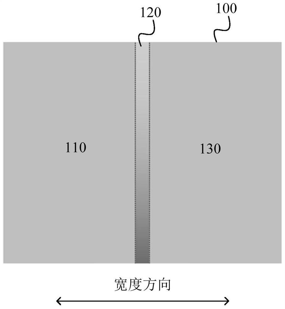
[0051] Select copper foil with a width of 665mm, refer to image 3 The copper foil surface is divided into a first coating area 110, a blank area 120 and a second coating area 130, the width of the first and second coating areas are both 315 mm, and the width of the middle blank area is 35 mm. A natural graphite slurry is applied in the first and second application zones. After the coated pole piece is baked, it is transferred to the rolling process. After the pole piece is rolled to the thickness specified by the process, it is transferred to the laser die-cutting process, so that the pole piece moves along the Figure 4 The two lasers (A, B) cut the tab in the horizontal direction according to the set program. The shape of the cut tab is isosceles trapezoidal, and the distance between two adjacent tabs is 50mm. Effect picture as Figure 5 shown.

Embodiment 2

[0053] Select aluminum foil with a width of 1320mm, refer to Figure 8 The copper foil surface is divided into a first coating area 110, a first sub-coating area 121, a blank area 120, a second sub-coating area 122 and a second coating area 130, the first and second coating areas The widths are both 300 mm, the widths of the first and second sub-coating areas are both 15 mm, and the width of the blank area in the middle is 30 mm. The lithium iron phosphate slurry is coated in the first and second coating areas, and the ceramic slurry is coated in the first and second sub-coating areas. The coated pole piece is baked and then transferred to the rolling process. After the pole piece is rolled to the thickness specified by the process, the pole piece is cut along the pre-slitting line 300 to obtain two small pole pieces. Transfer the two small pole pieces to the laser die-cutting process, so that the pole pieces move vertically at a certain speed, and the laser cuts the pole lug...


PUM

PropertyMeasurementUnit
widthaaaaaaaaaa
widthaaaaaaaaaa
widthaaaaaaaaaa

Abstract

The invention discloses a pole piece laser die-cutting method. The method comprises the following steps: (1) providing a foil; (2) dividing the surface of the foil into a first coated region, a blankregion and a second coated region, wherein the blank region is positioned between the first coated region and the second coated region; (3) coating electrode slurry to the first coated region and thesecond coated region, roasting and rolling a obtained pole piece in sequence to obtain a pole piece to be die-cut; and (4) utilizing laser to perform lug die-cutting on the blank region to obtain multiple first lugs and multiple second lugs, and dividing the pole piece to be cut into a first pole piece and a second pole piece. The pole piece laser-cutting method disclosed by the invention can cutthe foil while accomplishing lug die-cutting and forming, so that lug processing cost is greatly reduced.

Description

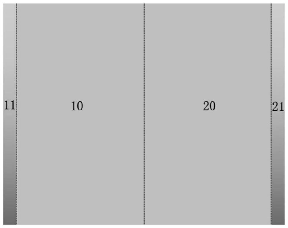
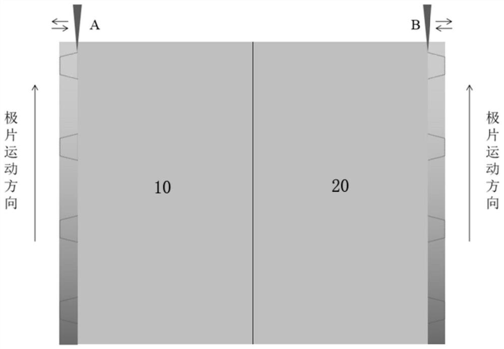
technical field [0001] The invention relates to the technical field of lithium battery production, in particular to a low-cost laser die-cut pole piece processing method. Background technique [0002] Laser die cutting is widely used in the tab forming of battery pole pieces due to its characteristics of small cutting burrs, low maintenance cost and high flexibility. At present, the tab forming schemes mainly include: 1. Slitting the pole piece first, and then performing laser die-cutting to realize the forming of the pole piece tab; Then slice it. In the above two schemes, the state of the pole piece incoming material is that the dressing area (10, 20) is in the middle, and the blank area (11, 21) is on both sides, such as figure 1 shown. During laser die-cutting, the pole piece moves vertically, and the laser moves back and forth horizontally, which is the S-shaped lug cutting process mentioned in the industry. The production process is as follows: figure 2 shown. ...

Claims


Application Information

Patent Timeline
Patent Type & Authority Applications(China)
IPC IPC(8): B23K26/38B23K26/70H01M2/26B23K101/36
CPCB23K26/38B23K26/70B23K2101/36Y02E60/10
Inventor 李奎秦跻龙柴成斌杨重科
Owner 昆山聚创新能源科技有限公司
Learn More