Supercharge Your Innovation With Domain-Expert AI Agents!

Energy-saving corrosion-resistant high-efficiency heat exchange device

A heat exchange device and high-efficiency technology, applied in indirect heat exchangers, lighting and heating equipment, combustion methods, etc., can solve problems that affect the safety of equipment operation, reduce the thermal efficiency of heat exchangers, and corrode metal heat exchange equipment. , to solve the problem of acid dew corrosion, save desulfurization process water, and prevent acid dew corrosion

Pending Publication Date: 2020-09-18
江苏龙净节能科技有限公司
View PDF0 Cites 0 Cited by
  • Summary
  • Abstract
  • Description
  • Claims
  • Application Information

AI Technical Summary

Problems solved by technology

The condensed water in the thermal system of the steam turbine absorbs the heat of the exhaust gas in the low-temperature economizer, reduces the temperature of the exhaust gas, is heated by itself, raises the temperature, and then returns to the low-pressure heating system of the steam turbine. However, coal, oil, and natural gas are all sulfur-containing fuels. , Combustion will produce sulfur dioxide and sulfur trioxide. Among them, sulfur trioxide and water vapor will produce sulfuric acid vapor under certain temperature conditions. The critical temperature at which this reaction can occur is called acid dew point. The metal wall surface in the boiler tail equipment If the temperature is lower than the condensation point (acid dew point) of sulfuric acid vapor, liquid sulfuric acid (acid dew) will be formed on the surface, which will corrode the metal heat exchange equipment, may cause leakage, and affect the operation safety and service life of the equipment. At the same time, the ash in the flue gas will adhere to the outer wall of the heat exchanger, reducing the thermal efficiency of the heat exchanger.

Method used


Image

  • Energy-saving corrosion-resistant high-efficiency heat exchange device
  • Energy-saving corrosion-resistant high-efficiency heat exchange device
  • Energy-saving corrosion-resistant high-efficiency heat exchange device

Examples


Embodiment Construction

[0045] In order to make the object, technical solution and advantages of the present invention clearer, the present invention will be further described in detail below in conjunction with the accompanying drawings and embodiments. It should be understood that the specific embodiments described here are only used to explain the present invention, not to limit the present invention.

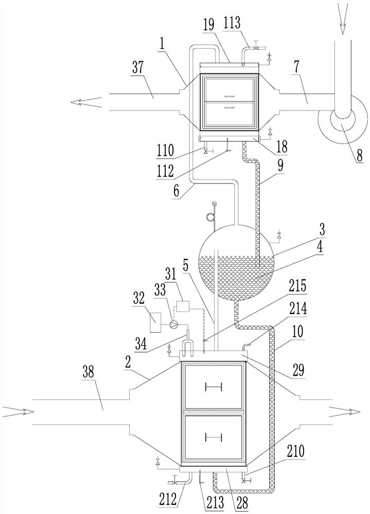
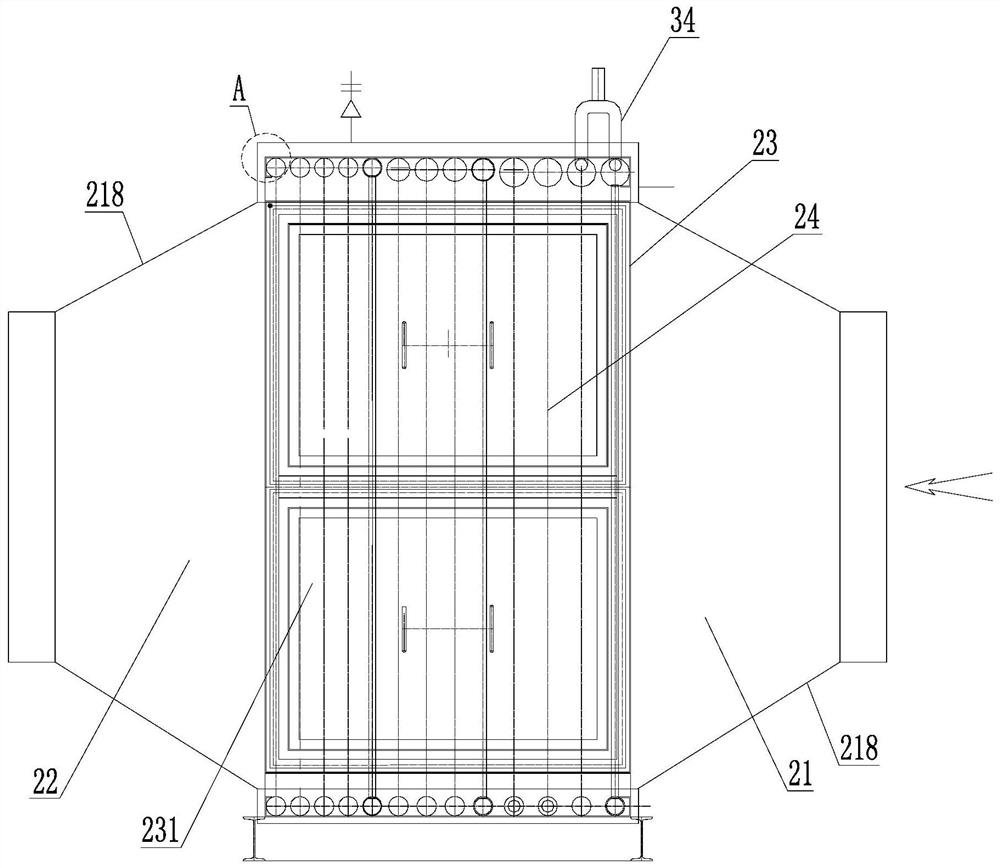
[0046] Such as figure 1 As shown, the energy-saving, corrosion-resistant and high-efficiency heat exchange device includes: two phase-change heat modules arranged up and down, and the phase-change heat module located on the upper side is defined as phase-change heat release module 1, and the gaseous work After passing through the phase change exothermic module, the substance is transformed into a liquid working medium due to heat dissipation; the phase change heat module located on the lower side is defined as the phase change endothermic module 2, and the liquid working medium is transformed due t...


PUM


Abstract

The invention discloses an energy-saving corrosion-resistant high-efficiency heat exchange device. The energy-saving corrosion-resistant high-efficiency heat exchange device comprises a phase change heat release module, a phase change heat absorption module and a gas-liquid separation tower, wherein the phase change heat release module and the phase change heat absorption module are arranged up and down; the gas-liquid separation tower is arrange between the phase change heat release module and the phase change heat absorption module; an upper gas collecting pipe in the phase change heat absorption module communicates with the lower end of a first ascending pipeline; the upper end of the first ascending pipeline extends upwards into the gas-liquid separation tower and is positioned in theupper space of the gas-liquid separation tower; the top of the gas-liquid separation tower communicates with an upper gas collecting pipe in the phase change heat release module through a second ascending pipeline; an induced draft fan is arranged at a gas inlet of the phase change heat release module; the bottom of a lower liquid collecting pipe in the phase change heat release module communicates with the upper end of a first descending pipeline; the lower end of the first descending pipeline extends into the gas-liquid separation tower and is immersed in liquid working medium in the lower space of the gas-liquid separation tower; and the bottom of the gas-liquid separation tower communicates with a lower liquid collecting pipe in the phase change heat absorption module through a seconddescending pipeline. The energy-saving corrosion-resistant high-efficiency heat exchange device has the advantages of energy saving and corrosion resistance.

Description

technical field [0001] The invention relates to the technical field of energy-saving equipment in industries such as electric power, chemical industry and metallurgy, and in particular to an energy-saving, corrosion-resistant, high-efficiency heat exchange device. Background technique [0002] Boiler exhaust heat loss is one of the main heat losses in power plant boilers. Exhaust heat loss accounts for the largest proportion of all heat losses in famous coal-fired boilers, accounting for more than 75% of the total heat loss of coal-fired boilers. The main factor leading to the heat loss of the exhaust gas is the exhaust gas temperature. Generally, when the temperature of the exhaust gas increases by 10°C, the heat loss of the exhaust gas increases by 0.6%-1%, and the heat consumption increases by 1.2%-2.4%. In addition, too high exhaust gas temperature will not only seriously reduce the utilization rate of energy, but also greatly affect the subsequent desulfurization flue g...

Claims


Application Information

Patent Timeline
IPC IPC(8): F23L15/04F28D15/02F28D15/06
CPCF23L15/045F28D15/0266F28D15/06Y02E20/34
Inventor 陈晓雷钟志良魏树林吴长森彭文熙顾建清
Owner 江苏龙净节能科技有限公司
Features
  • R&D
  • Intellectual Property
  • Life Sciences
  • Materials
  • Tech Scout
  • Unparalleled Data Quality
  • Higher Quality Content
  • 60% Fewer Hallucinations
Learn More