Cu powder applied to laser cladding of P-Cu work piece, and cladding method

A laser cladding and workpiece technology, applied in metal material coating process, coating, etc., can solve problems such as cooling overspeed, changing the comprehensive performance of cladding layer, easy cracking of weld bead, etc., to achieve smooth curve, similar performance, The effect of dense tissue structure

Active Publication Date: 2020-09-22
鞍山大族激光技术有限公司
View PDF9 Cites 1 Cited by
  • Summary
  • Abstract
  • Description
  • Claims
  • Application Information

AI Technical Summary

Problems solved by technology

[0005] 3) At the beginning of cladding, in order to reduce the excessive demand for laser energy density, the use of aluminum-based admixtures changes the overall performance of the cladding layer and makes it difficult to control the cladding bead effect;
[0006] 4) During cladding molding, the weld bead is easy to crack due to excessive cooling;
[0007] 5) When cladding is lapped, due to multiple laps, excessive heat accumulation is caused, and the thin-walled substrate is easily deformed;
[0008] 6) After the cladding is completed, the material difference between the cladding layer and the base material is too large, which will cause excessive gradient results in the hardness, wear resistance, corrosion resistance, electrical conductivity, heat conduction and mechanical comprehensive properties of the final workpiece

Method used


Image

  • Cu powder applied to laser cladding of P-Cu work piece, and cladding method
  • Cu powder applied to laser cladding of P-Cu work piece, and cladding method
  • Cu powder applied to laser cladding of P-Cu work piece, and cladding method

Examples


Embodiment

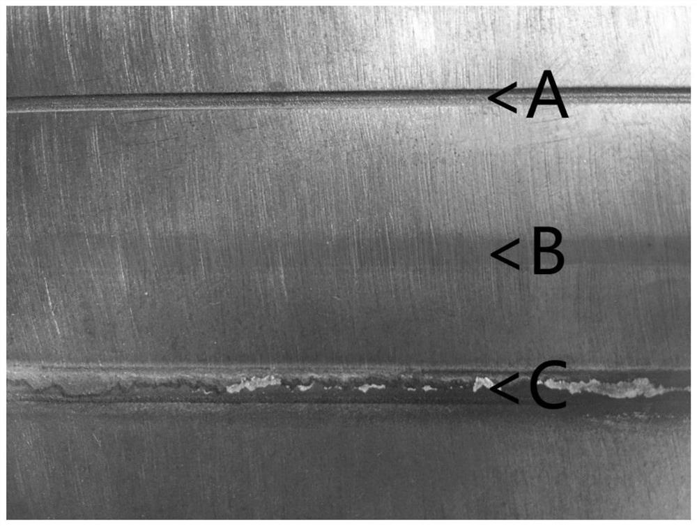
[0043] refer to image 3 and Figure 4 , select a base material of a phosphor bronze workpiece, draw three grooves on the base material, and one groove as a control, without treatment ( image 3 and Figure 4 number A position), the other two grooves ( image 3 and Figure 4 Number B, C position) Utilize the method of the present invention to carry out laser cladding, cladding steps are:

[0044] 1) Surface pretreatment, including the following treatment procedures:

[0045] 101) Utilize acetone to wash off the large area of ​​oil stains on the cladding surface of the workpiece, and wash with water;

[0046] 102) Ultrasonic removal of oil stains in workpiece pores, washing with water;

[0047] 103) Utilize 8-13% dilute hydrochloric acid to wash to remove oxides on the surface of the workpiece, and wash with water;

[0048] 104) polishing, twice washing;

[0049] 105) Micro-etch the surface of the workpiece with micro-etching solution, perform surface activation treatme...


PUM


Abstract

The invention belongs to the technical field of laser cladding and particularly relates to Cu powder applied to laser cladding of a P-Cu work piece, and a cladding method. The Cu powder comprises thefollowing components: 2.5-9% of Sn, 0.05-0.6% of P, 0.01-0.05% of Pb, 0-0.5% of Ce, 0-1% of Y, 0-0.2% of Sm and the balance being Cu and inevitable sundries. The method comprises the following steps:carrying out pre-processing on the surface of the work piece; carrying out tinning on the surface of the work piece; manufacturing a work piece cooling supporting base for a cladding process; preparing the Cu powder applied to laser cladding of the P-Cu work piece and drying the Cu powder; fixing the work piece above the cooling supporting base, carrying out cooling in the cladding process, irradiating a cladding position on the surface of the work piece by a laser, feeding the Cu powder to the cladding position on the surface of the work piece by a synchronous powder feeding machine, and carrying out laser cladding on the surface of the work piece; carrying out abrasive blasting on the surface of the cladding position; and carrying out processing and shaping of the work piece. According to the invention, metallurgical bonding of a cladding layer and a work piece base material is presented, and the organizational structure is compact without gas holes or cracks. Results of hardness, wear resistance and corrosion prevention experiments show that transition between the cladding layer and the work piece base material is natural, performance is simple, and curves are steady.

Description

technical field [0001] The invention belongs to the technical field of laser cladding, and in particular relates to a copper powder for laser cladding of a phosphor copper workpiece and a cladding method. Background technique [0002] Among the existing phosphor copper surfacing repair technologies, only laser cladding technology can achieve metallurgical bonding effect and batch processing under the premise of extremely small heat input. However, in the actual production process, due to the high reflectivity and material characteristics of copper alloy materials for common semiconductor lasers, the cladding has the following problems: [0003] 1) Before cladding, the adhesive or light absorbing agent applied to increase the light absorption rate of the substrate enters the molten pool, causing adverse effects; [0004] 2) Before cladding, the surface is pretreated with nickel-based materials, which changes the comprehensive performance of the bonding area and the additive ...

Claims


Application Information

Patent Timeline
Patent Type & Authority Applications(China)
IPC IPC(8): B22F1/00C23C24/10C22C9/02
CPCB22F1/0003C23C24/103C22C9/02
Inventor 马思春孟鹤来
Owner 鞍山大族激光技术有限公司
Why Eureka
Try Eureka